SEL-3031 Instruction Manual Date Code 20181001
Installation
Connections
2.12
Connections
Rear-Panel Connections
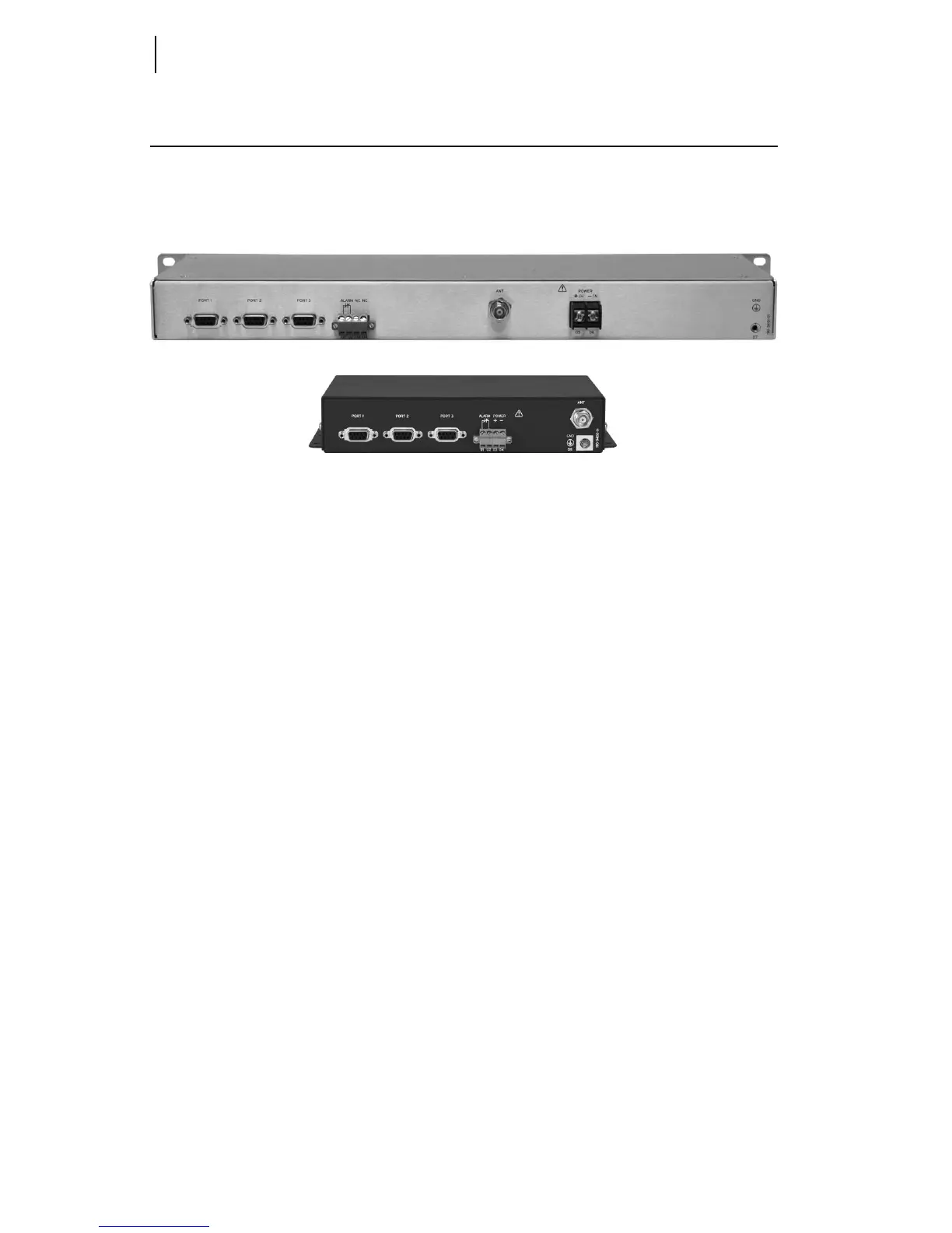
The physical layout of the SEL-3031 connections is shown in Figure 2.5.
Figure 2.5 Wall-Mount and Rack-Mount Rear Connections
Power Connections
The POWER terminals on the rear panel (labeled +/H and -/N) must connect to the
correct supply voltage. The supply voltage range is located on the serial label. The
wall-mount configuration accepts only 9–30 Vdc. The rack-mount configuration
accepts 24–48 Vdc or 125/250 Vac or Vdc. Check the serial label for power supply
information.
Do not apply power to the SEL-3031 without having a proper 50-: load on the antenna
port. If you do not have the proper 50-: load connected, the radio antenna port will
shut off, the alarm contact will pulse, and the
ALARM LED will illuminate. This
functionality protects the radio circuitry and indicates an antenna or cable failure. The
POWER terminals on the rack-mount version are isolated from chassis ground. The
POWER terminals on the wall-mount version are not isolated from chassis ground. Use
2.5 mm
2
(14 AWG) size wire to connect to the POWER terminals on the rack mount.
Place an external circuit breaker or switch no more than 3 m (10 ft) from the
equipment. The circuit breaker (or equivalent approved disconnect device appropriate
for the country of installation) must comply with IEC 60947-1 and IEC 60947-3, be
identified as the disconnect device for the equipment, and be located near the
equipment. This disconnect device must interrupt both the hot (+/H) and the neutral
(–/N) power leads. The maximum current rating for the power disconnect circuit
breaker or overcurrent device (fuse) must be 20 A. An internal power supply fuse
protects the operational power supply. Be sure to use fuses that comply with
IEC 60127-2.