Atmospheric electrical charge accumulation can cause potential between the conductor and shield
of the feedline, or cause lightning to strike an antenna. A lightning protector should be installed to
prevent damage to equipment or injury to personnel.
Mounting the antenna on an equipment building roof or tower is safest because the
potential rise on the outside of either of these structures will approximately equal the
potential on the inside. A lightning protector (Radio Surge Protector, SEL part number
200-2004) should be used to equalize the difference in potential that can occur between
the center conductor and the shield of the coaxial cable between the antenna and the
radio. The higher the antenna is mounted on a support structure, the greater the
probability of equipment damage resulting from a lightning strike.
In all surge-protector applications, you should mount the surge protector at the building
or enclosure entrance, and ground the surge-protector body. Ground the radio to the
same point as the surge-protector ground to avoid ground-rise-potential damage.
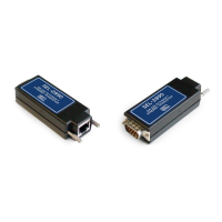
When using the surge protector, order an additional SEL-C964 or SEL-C966 cable and
place this cable between the SEL-3031 and the surge protector. Because the distance
varies from the SEL-3031 to the surge protector, be sure to specify this cable at
approximately the correct length (plus 10 to 20 percent for installation variability).
Grounding (Earthing) Connections
You must connect the ground terminal labeled GND to a rack frame or
switchgear ground for proper safety and performance. Use 2.5 mm
2
(14 AWG)
wire less than 2 m (6.6 ft) in length for the ground connection.
Serial Ports
Because all ports (1, 2, and 3) are independent, you can communicate to any
combination simultaneously. All EIA-232 ports accept DB-9 male connectors. The
serial port EIA-485 option for Port 1 is also a DB-9 male connector. If Port 1 is ordered
with the EIA-485 option the product will ship with a DB-9-to-terminal adapter to
easily wire to EIA-485 systems. Port 2 includes the IRIG-B time-code signal input (see
Table 2.8). SEL offers fiber-optic transceivers or fiber-optic port options on Port 1
(SEL-2812 and SEL-9220 compatible fiber-optic) for connecting devices at distances
over 15 meters (50 feet) where copper cable is not appropriate. The SEL-2800 family
of transceivers provides fiber-optic links between devices for electrical isolation and
longer distances, overcoming the limitations of electrical EIA-232 interfaces. Contact
SEL for further information on these products.