SEL-3031 Instruction Manual Date Code 20181001
Installation
Overview
2.10
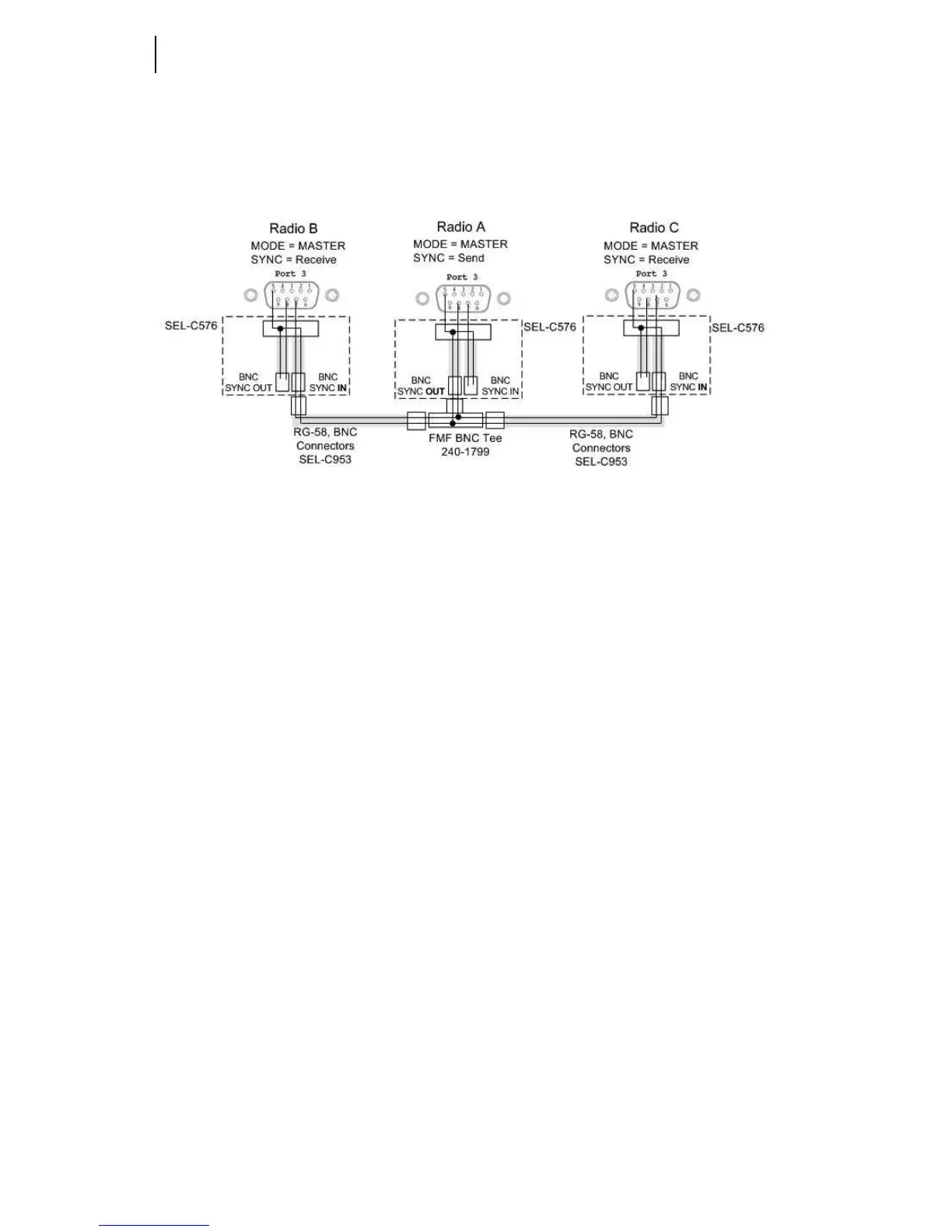
shows an example of how you would connect three collocated radios by using
SEL-C576 cables along with BNC Tee and BNC coaxial cables. The BNC Tee and
coaxial cables allow you to add more radios while utilizing one radio as the master
sync radio (see Section 3: Job Done Examples).
Figure 2.4 Three Collocated Synchronized Radios
Installing Collocated Antennas
SEL Hop-Sync™ technology provides the ability to install multiple radios at one
location and mitigate the interference typically seen from adjacent antenna links. SEL
Hop-Sync technology allows you to place antennas within feet of each other and still
maintain a strong signal link. If the application for using the radios with SEL Hop-
Sync technology is for non-critical data and the dependability is low then the antennas
can be placed within 8–10 feet of each other and still provide proper operation.
The failure modes of the SEL Hop-Sync systems vary by application and by how many
antennas are collocated. If you have a system with two collocated antennas using SEL
Hop-Sync technology and one of the radios loses power then the system will still work
properly. In the same condition, if you lose the synchronization cable between the two
radios then they will interfere with each other and the radio signal will be degraded to
the point of loss-of-link depending on the distance between radios. When using the
radios in collocated applications with M
IRRORED BITS or other critical
communications, additional setup is needed to validate that if the radios become
unsynchronized the radio links will still operate as expected with an acceptable level of
dependability. Performing the following five steps helps to identify how far apart the
antennas need to be to provide adequate link availability if synchronization is ever lost.
This example follows the configuration shown on Figure 2.4.
Step 1. Setup the three locations as shown in Figure 2.3 and verify each link
works independently.
Step 2. Leave the link from Radio A1 to B on and turn the power off on
Radio A2 and C.