SEL-3031 Instruction Manual Date Code 20181001
Installation
Overview
2.8
Antenna System Ground
Antenna system grounding is not included in the scope of this manual. Please consult a
radio systems engineer or other professional for advice on ground-system design. A
well-designed system will minimize equipment damage and risk of electric shock to
personnel.
Chassis Ground
Connect the grounding terminal labeled GND on the rear panel to a rack frame
ground or main station ground for proper safety and performance. Use 4 mm
2
(12 AWG) or heavier wire less than 2 m (6.6 ft) in length for this connection.
The ground connection should be made before the power connections.
Collocated Antenna Systems
Many radio systems today consist of having multiple radios at one location. The
multiple radios are needed for either directed P2P links, multiple data needing to reach
different locations, or for a primary/backup scheme. In these cases, it is desirable to
install the antennas on the same pole or within close proximity to reduce cost.
Installing multiple antennas in close proximity operating on the same frequency band
can cause large amounts of adjacent channel interference. This adjacent interference
can greatly degrade the availability and dependability of each link. Take the example of
two P2P links where two of the antennas are at one location and the links terminate at
two different locations (see Figure 2.3).
1-1/4-inch
HELIAX
Do not use Do not use 0.95 dB 2.85 dB
1-5/8-inch
HELIAX
Do not use Do not use 0.80 dB 2.4 dB
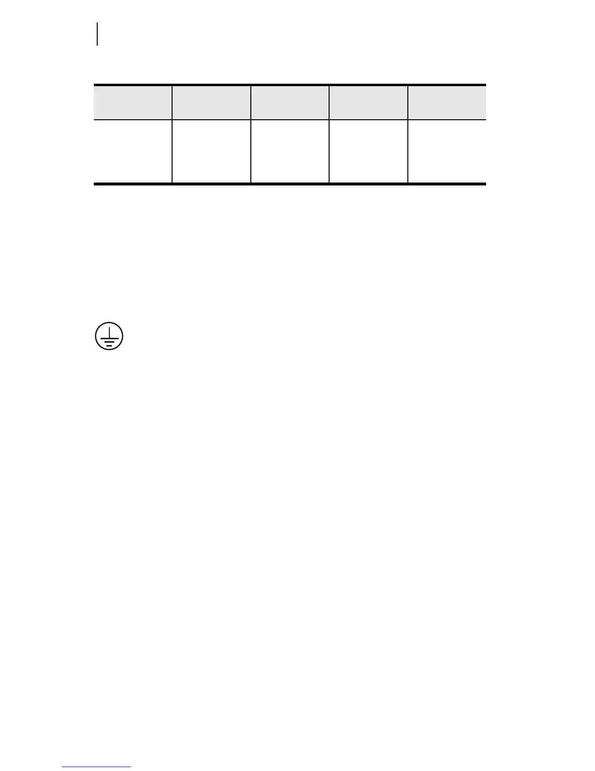
Table 2.5 Length vs. Loss in Coaxial Cables at 900 MHz (Sheet 2 of 2)
Cable Type
3.05 meters
(10 feet)
12.24 meters
(50 feet)
30.48 meters
(100 feet)
91.44 meters
(300 feet)