SEA SYSTEMS
INSTALLATION AND USE MANUAL
CONTROL PANEL and PREWIRED SYSTEM STK1
For Electric and Hydraulic Lifts
MSTK12-GB
Rev.01
30/12/05
SETRONIK1 Pagina 15 di 54
2.7.3.F
IXING AND CONNECTION OF THE SHAFT SENSORS FOR HYDRAULIC LIFTS
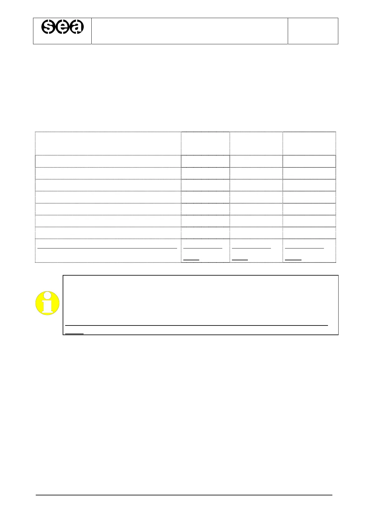
The shaft sensor kit can be of tree different type according to the type of brackets used for
sensors and magnets as the following tablet.
The tablet reports also the code of the diagram of the shaft sensor disposition included in
this paragraph.
SENSORS AND MAGNETS A TYPE
KIT BRAKET
B TYPE
KIT BRAKET
C TYPE
KIT BRAKET
Sensors IS, ID, C, D, FCE(optional) CFR CFR G-CFR
Sensors SR, DR, DS CVR SR, DR, DS SR, DR, DS
Magnet bars to command IS, ID, C, D MFR MFR G-MFR
Round magnet couple to command SR MVR-SR No Bracket G-MVR-SR
Round magnet couple to command DR MVR-DR No Bracket G-MVR-DR
Round magnet couple to command DS MVR-DS No Bracket G-MVR-DS
Diagram for sensor and magnet disposition
Æ
See diagram
CVIA
See diagram
CVIA
See diagram
CVIC
HIGHLIGHT
We recommend that you choose A System or C System for the installation of
magnets. The system ensures tighter fastening of the magnets, a better magnetic
field, less exposure to various bodies (grease, iron fillings….)
With the B System, the magnets without bracket have to be fixed directly on the
guide.