1 - 79
(the standard surface), the distance between zero point and the standard block is set to the
parameters (No.6249~6251). Also, by measuring from Z axis direction, safety guard
parameters (No.6258~6259) are set at the same time. Be sure to return to the previous
screen by pressing F2/REF. GAUGE .
(4) Select an offset number to be set by the page key and the cursor key.
(5) Have the tool come into contact with the reference gauge.
→NC automatically judges the axis of which the touch sensor signal comes on, and the tool
offset amount is automatically written in.
X, Y-axis ..... Tool diameter is calculated and the tool shape compensation amount
for diameter compensation is rewritten.
Z-axis ..... Tool length is calculated and the tool shape compensation amount for
length compensation is rewritten.
(6) When the setting of all the necessary offset amounts for the tool is completed, let the tool
setter screen OFF.
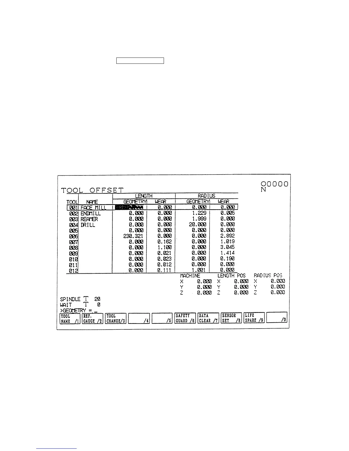
Fig. 1.8 Tool (Compensation)
(Note 1) When writing in a tool diameter, if measurements are repeated several times without
changing the designated offset No., the offset amount is rewritten only when the result
of a later measurement gives a larger value than that of previous one. If the
designation of the offset No. is changed or tool setter button is pressed anew,
however, the first measurement result is written in as the offset amount.
(Note 2) The reference gauge means the contact surface of a reference block. When using a
touch sensor on a table other than a reference block, the reference gauge means its
contact surface.
 Loading...