1 - 67
Indication of rotating angle (Horizontal, Vertical)
Drawing zone (Maximum, Minimum)
Indication of drawing for each tool (Color designation)
Selection of cutting feed line
Selection of rapid traverse line
Color designation for drawing dot lines.
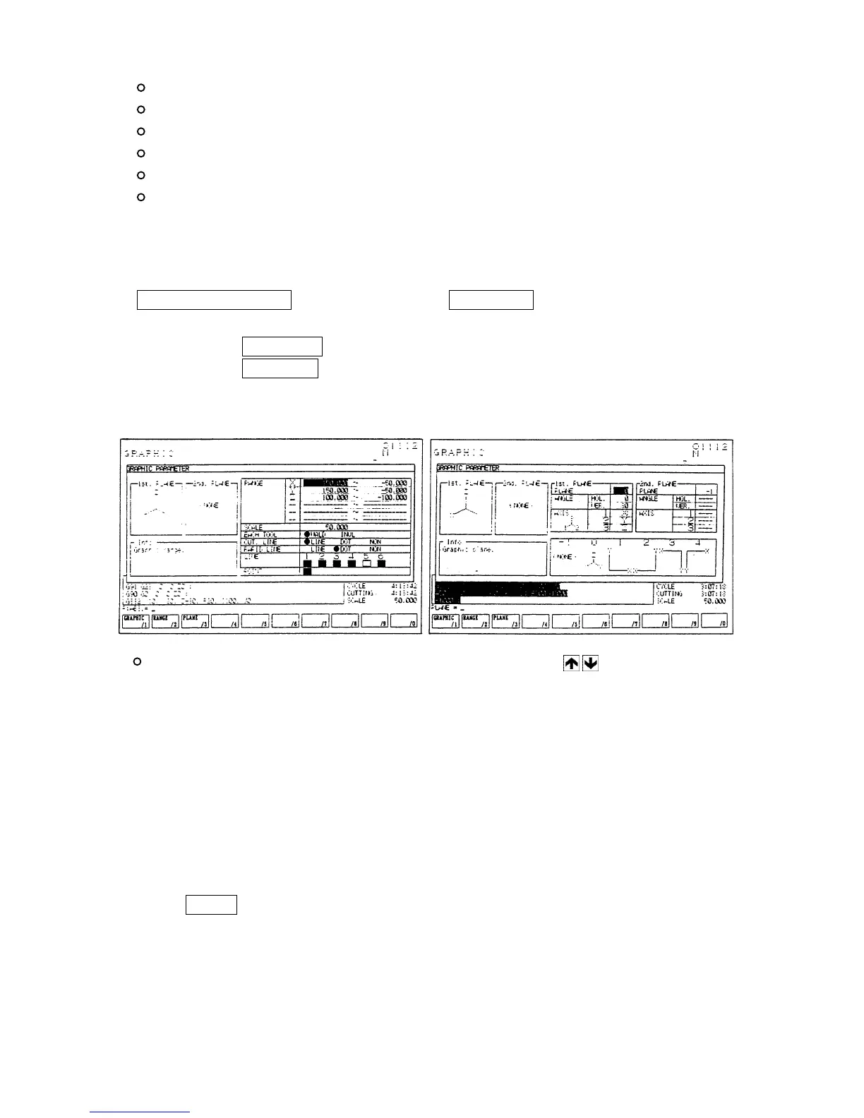
14-2 Drawing Parameter
The drawing parameter screen is overlapped with the drawing screen when pushing the
F1/GRAPHIC PARAM. of the drawing screen ( F7/GRAPH. ).
By pressing the F2/RANGE key, the display changes into the range setting screen.
By pressing the F3/PLANE key, the display of plane setting screen can be called up.
GRAPHIC parameter (Range setting) GRAPHIC parameter (plane setting)
Setting parameter for drawing: Move the cursor by cursor keys to the parameter
column to be set. Brief explanation is displayed on the
explanation column.
[Range setting]
(1) Drawing zone
Set the maximum or minimum value of each axis to draw.
Center coordinate (mean value of max. or min. value) and magnification (Max, and min.
value are shown in the screen.) are decided.
Input a coordinate value (work coordinate) in the key input area and decide it by pressing
the INPUT key.
In this case the maximum value should be set larger than the minimum value.
 Loading...