1 - 78
(Note 1) When the system is reset in the midst of the setting operation (during 2nd or
3rd point is being measured), the system returns to the initial status (the status
to be ready for the 1st point measurement).
(Note 2) The mutual distances between the 3 points is short against the parameter
setting (No.6257), the measurement cannot be made and a commentary
message is displayed accordingly. By resetting, the status is released and the
system is initialized.
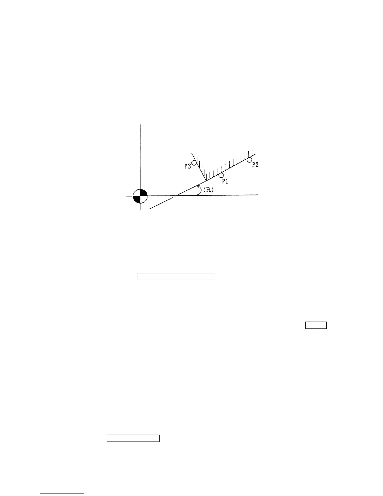
(Note 3) Command G code of axis rotation in the program to operate by rotating the
coordinate.
Determine a corner position at the point where a line through the points P1 and P2,
and a vertical line through P3 cross.
This axis rotation angle (R) is that between a line through P1 and P2, and X-axis.
16-6 Manual Overwriting of Work Zero Point Offset Amount.
(1) Press the function key F4/WORK COORDINATE for selecting the work coordinate
(modify) screen (Fig. 1.8).
(2) Select the work zero point offset amount to be set by the page key and the cursor key.
(3) At first, press [P] (input the given amount as work zero point offset amount) or [I] (input the
given amount added as work zero point offset amount). Next, select an axis to be inputted
by the cursor key, or press axis name to be inputted, and press [Numerical value] INPUT
which overwrites the specified work zero point offset amount.
16-7 Setting Operation of Tool Setter
(1) Return the basic 3 axes to manual reference point. Install the standard block on the table
or the touch censor on the table.
(2) Turn on the tool setter by manual mode.
(3) Set the distance from the zero point to the standard block to the parameters (No.
6249~6251). When this value is fixed, the operation in this item is unnecessary. When
position of the standard gauge is not fixed, following operation to set a correct value is
necessary.
By pressing F2/REF. GAUGE parameters (No.6249~6259) are displayed. When the
touch probe is touched to the standard block, by the same calculation as the work setter
Y axis
X axis
 Loading...