© by SEMIKRON / 2017-09-07 / Technical Explanation / SKiiP
4
Page 12/73
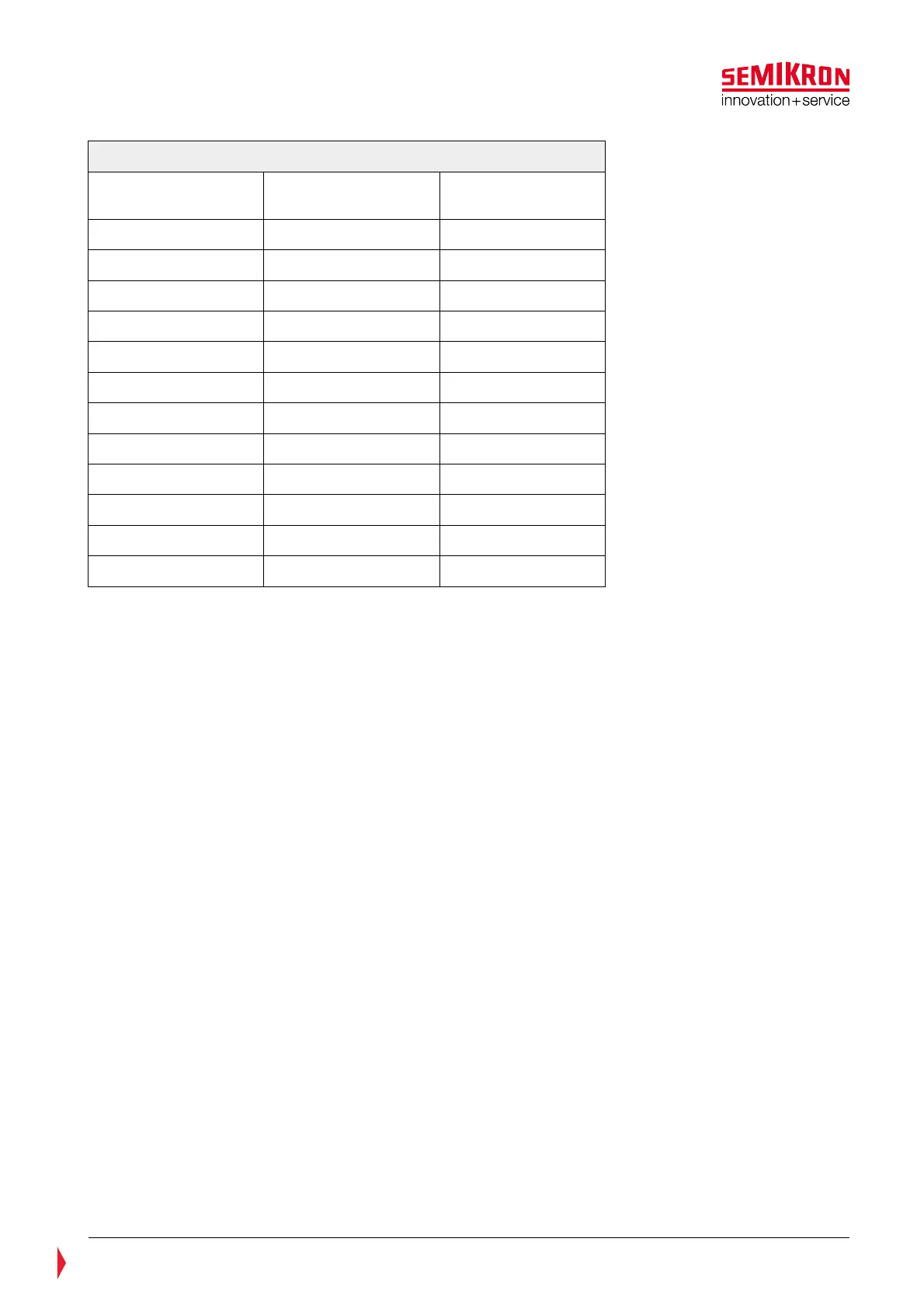
Table 4—4: Altitude correction factors (IEC 60664-1)
Altitude Normal barometric
pressure
Multiplication factor
for clearances
m kPa
2 000 80,0 1,00
3 000 70,0 1,14
4 000 62,0 1,29
5 000 54,0 1,48
6 000 47,0 1,70
7 000 41,0 1,95
8 000 35,5 2,25
9 000 30,5 2,62
10 000 26,5 3,02
15 000 12,0 6,67
20 000 5,5 14,5
The overvoltage category influences the installation altitude, too. In order to increase the installation
altitude further the overvoltage category needs to be reduced (EN50178):
“As an alternative to the values of table 3, columns 2 to 5 (of the cited standard), the clearance between
mains-circuits of an EE and its environment may be designed in accordance with overvoltage category II, if
facilities are provided which reduced overvoltages of category III to values of category II…However for
reinforced isolation according to column 7 (of the cited standard) shall not be reduced.”
The required clearance distances between mains-circuits and their environment for overvoltage category II
are listed in EN50178.
If safety isolation is necessary the maximum altitude of SKiiP
®
4 is 6250 m (690 TN grid and overvoltage
category II).
If only basic isolation is required even higher operation altitudes are possible. In case of a 690V TN grid
and overvoltage category II an altitude of theoretically 9000 m for SKiiP
®
4 is possible.
This is the case when an additional basic isolation is implemented between the SKiiP 4 driver interface and
controller board. This can be realized by the following means:
• Use of fiber optic for control signals (TOP, BOT, Error) and
• SKiiP analogue signals (current, DC-voltage and temperature measurement) are not used and
• all SKiiPs are supplied by separate power supplies to which no other circuit is connected.
The above described implementation is shown in Figure 4.3. The “F-Option board” for an optical fibre
based isolation of the SKiiP
®
4 (please refer to Figure 4.3) can be ordered separately and can be easily
mounted on the SKiiP
®
4 top cover.