© by SEMIKRON / 2017-09-07 / Technical Explanation / SKiiP
4
Page 47/73
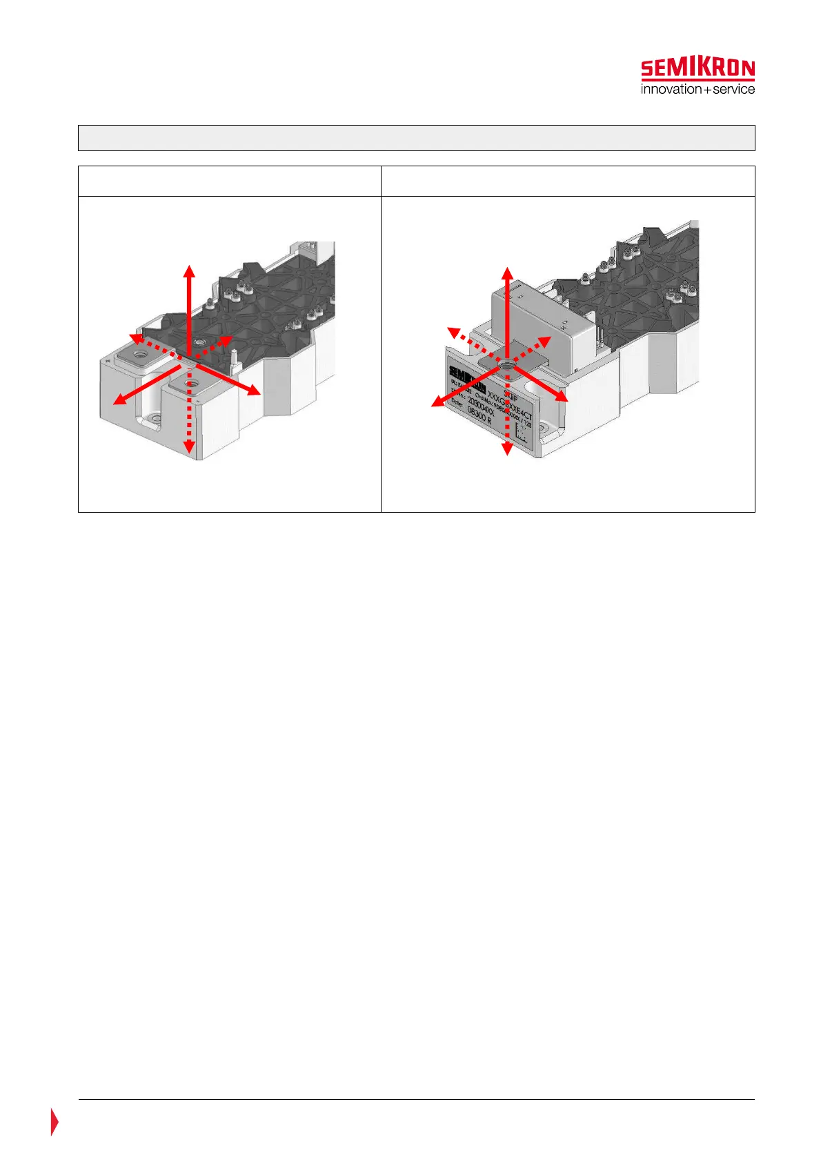
Figure 6.1: Maximum forces at the main terminals
DC-Terminals AC-Terminal
The following should be considered in the design process:
• DC connection:
• Mechanical tolerances, especially when larger DC-links are used which are connected on more than
one SKiiP
• Thermal expansion:
• The DC-link is heated up under load and expands mechanically. This causes mechanical forces on the
terminals.
• Stiffness of terminals for DC connection:
• The connections should be soft in order to minimize the mechanical forces. This can be realized e.g.
by using of tempered copper.
• Terminal hole diameter:
• Should be large enough that the screw fits through the hole into the SKiiP connection.
• Dimensions of the DC connections:
• Consider heating and isolation. The terminals must not heat up snubber capacitors.
• Symmetrical layout of DC connection
• The inductance between the terminals and the DC-link capacitor should be equal for a symmetrical
current sharing between the half bridges
AC connection:
• Symmetrical AC connections for symmetrical current sharing between the paralleled half bridge
modules. The load cable should be connected in the middle of the AC terminal and have equal distance
to the each half bridge module.
• Connect a plate (e.g. copper) on all AC terminals of one SKiiP
• Cables can be connected on the same plate but it has to make sure that the cables do not apply force
on the terminals (pull or push any direction). Therefore flexible cables with stress relief should be used.
• The plate should be fixed by fixing poles. These poles shall be mounted directly on to the heat sink or a
fixed frame construction and placed close to the SKiiP device.
The design has to be as depicted in Figure 6.2
F
+
F
+y
-Z
+Z
F
-y
+x
F
+y
F
-Z
F
+Z
F
-y