© by SEMIKRON / 2017-09-07 / Technical Explanation / SKiiP
4
Page 16/73
5.2 Gate driver interface “SKiFace”
5.2.1 Overview
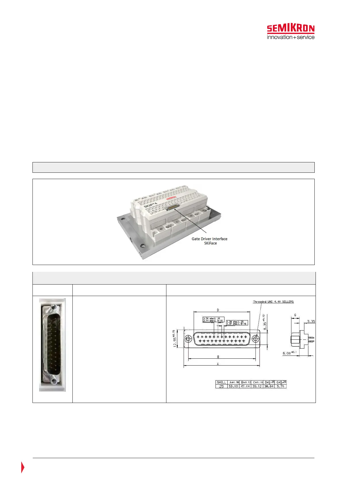
The Gate Driver Interface “SKiFace” is shown in the red colour marked frame of Figure 5.2. “SKiFace
defines the 25 pin D-Sub male plug connector and the corresponding signal assignment. The appearance of
the plug, its pin-out and dimensions are summarized in Figure 5.3.
The SKiFace interface provides pins for:
• External Power Supply
(refer to chapter 5.2.3)
• Switching signal input
(refer to chapter 5.2.4)
• Analogue signals (refer to chapter 5.2.5)
• HALT logic (refer to chapter 5.2.6)
• CMN_GPIO 1 output (refer to chapter 5.2.7)
• CMN_GPIO 2 (refer to chapter 5.3.6)
• CAN interface (refer to chapter 5.2.8)
Figure 5.2: Gate Driver Interface
Figure 5.3: SKiiP
4 - connector D-Sub 25 pin, male plug, vertical, top view
Picture Pin Configuration Dimensions
When connecting the SKiiP
®
4 to a control circuit the following recommendations shall be observed for a
proper cable selection:
• Cable length should be kept shorter than 3m
• Utilization of shielded cables is recommended
• Longer cables must be shielded