© by SEMIKRON / 2017-09-07 / Technical Explanation / SKiiP
4
Page 32/73
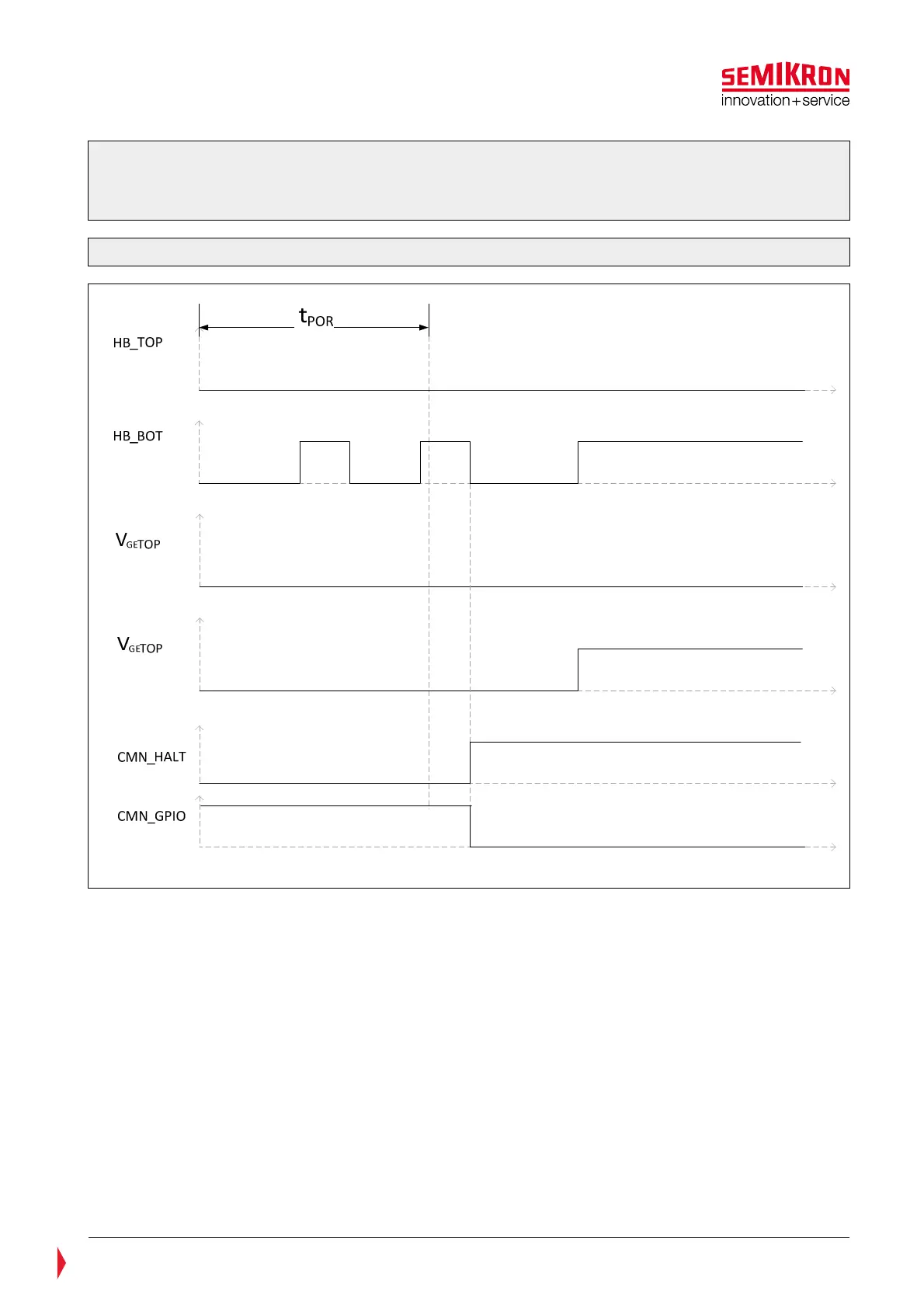
Please note: To ensure a high degree of system safety the TOP and BOT signal inputs must be kept in
LOW stat during driver’s boot up time. After the end of the power on reset, the IGBT operation is
permitted. The driver will stay in error mode if switching signals are applied during the boot-up
sequence as long as both switching signals are not LOW (see Figure 5.17).
Figure 5.17: Power-On-Reset timing diagramm
5.3.4 Interlock Dead Time Generation
The interlock dead time is defined as t
TD
in the SKiiP
®
4 data sheet.
The dead time circuit prevents that TOP and BOT IGBT of one half bridge are switched on simultaneously.
It is allowed to control the SKiiP
®
4 by inverted pulses, e.g. without controller generated dead time.
t
TD
is not added to a dead time provided by the controller (see Figure 5.18).
5.3.5 Short pulse suppression
The short pulse suppression time is defined as t
SIS
in the SKiiP
®
4 data sheet.
This function suppresses short turn-on and off-pulses at the pins HB_TOP and HB_BOT of the SKiFace
interface. In this way the IGBTs are protected against noise which can occur due to burst on the signal
lines. If a pulse is shorter than t
SIS
, it will be suppressed, the other channel will remain on. No error signal
will be issued.