© by SEMIKRON / 2017-09-07 / Technical Explanation / SKiiP
4
Page 29/73
5.2.9 Ground connection
The SKiiP
®
4 interface has got power grounds, digital grounds
and analogue circuit related grounds. The power ground and
digital ground are used for as reference for the power supply
and as the reference of digital signals, respectively. The
analogue ground is used to achieve a more accurate interface
of measured analogue signals. All grounds are physically
interconnected on the gate driver board. It is allowed to
short-circuit all ground potentials except the analogue ground
on the user controller board.
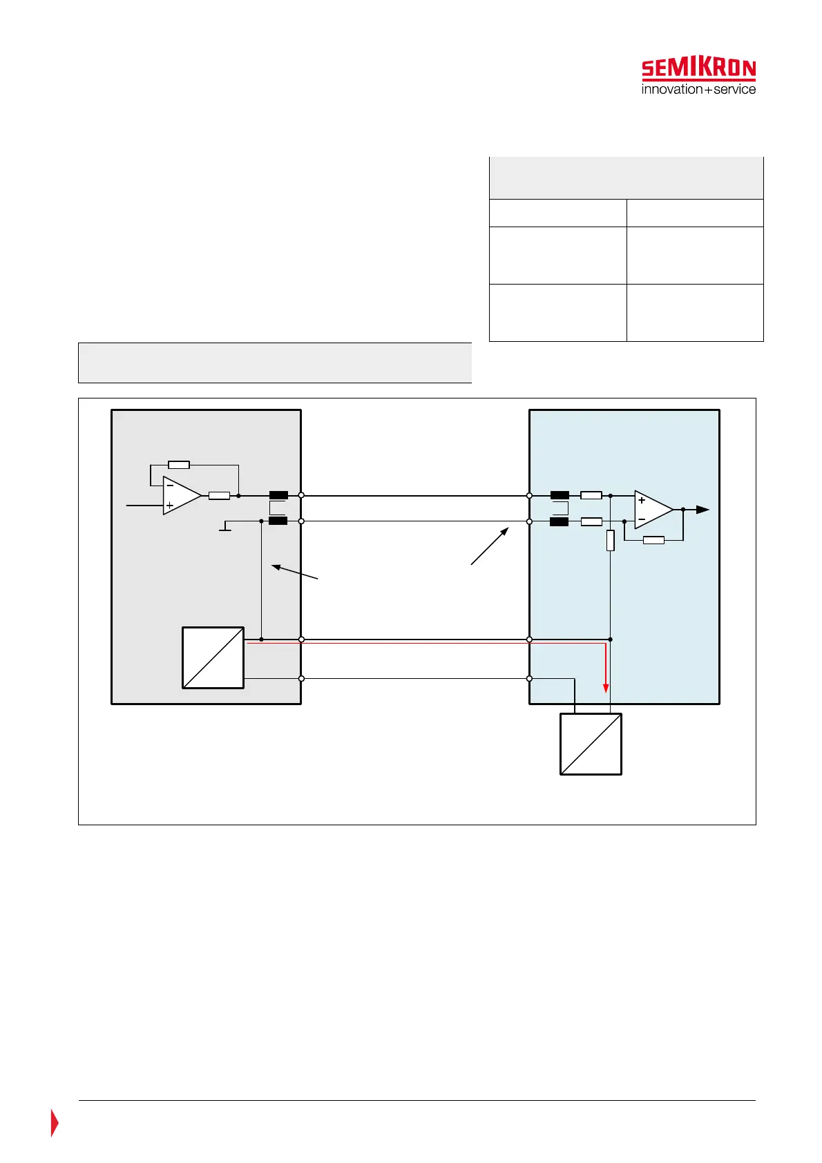
The analogue ground should be used as reference to
differential amplifier inputs on the controller board to ensure
accurate measurement (refer to Figure 5.13).
Figure 5.13: Prevention of ground loops by
differential amplifier circuitry
HB_I = Current signal
HB_I_GND = Analogue ground
Pin 23
Pin 10
Analogue inputAnalogue output
DC
DC
DC
AC
External Power Supply
V
s
GND
Pin 14, 15, 16
Pin 1, 2, 3
High impedance path for
supply current
Driver Board User Controller Board
Supply current
5.2.10 Shield and protective earth/chassis connection
The shield of the D-Sub connector is connected to GND at the gate driver board. There is no connection at
the gate driver board to heat sink nor to any other protective earth connections. On the user controller
board the shield should be connected to the chassis which is linked to Protective Earth (PE) in insulation
class 1 systems. This single ended grounding is effective against capacitive coupling e.g. from neighbouring
conductors since the grounded shield forms the opposite pole of the parasitic capacitance. The interference
current flows away via the shield. The GND of the user controller board can be connected to protective
earth/chassis either directly or by a suitable capacitor. This connection should be low inductive (e.g. metal
bolts from PCB to chassis) and located close to the D-Sub connector. Furthermore each signal output and
input should have a capacitor to chassis. These measures are for bypassing burst signals.
Table 5—3: Ground connections of
SKiiP
®
4
Function Signal
Power ground and
digital grounds
PWR_GND
CMN_GND
HB_GND
Analogue ground CMN_TEMP_GND
CMN_DCL_GND
HB_I_GND