© by SEMIKRON / 2017-09-07 / Technical Explanation / SKiiP
4
Page 43/73
5.3.8.3 DC-Link Voltage Sensing
The DC-link voltage (V
DC
) is sensed on the secondary side of the driver board between the DC plus and DC
minus terminal. After digitizing and transmitting the measured value to the primary side via a galvanic
isolation, the digital value is converted back to an analogue signal on the primary side. The analogue DC-
link voltage signal is available on the SKiFace interface (see Table 5—1) with the characteristic given in
Table 5—10.
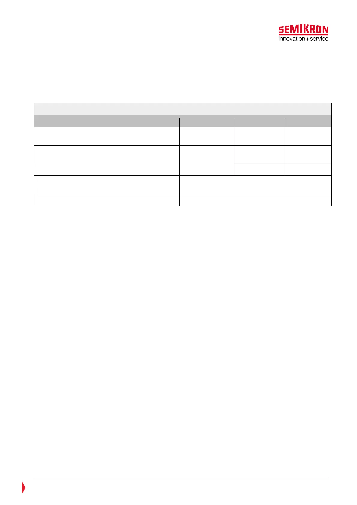
Table 5—10: V
characteristics
V
signal characteristics 1200V System 1700V System 1500V PV
Analogue DC-link voltage signal CMN_DCL @
900V
9V 6,75V 6,3V
Analogue DC-link voltage signal CMN_DCL @
1200V
9V 8,4V
Voltage ratio 10mV/V 7,5mV/V 7mV/V
Accuracy of analogue signal @ V
DCTrip
over full
temperature range
±3%
Phase shift, f0
1,8kHz
The characteristic between the DC-Link voltage and the signal on CMN_DCL for 1200V and 1700V SKiiP
®
4
systems can be found in the Figure 5.32 and Figure 5.33 corresponding.