© by SEMIKRON / 2017-09-07 / Technical Explanation / SKiiP
4
Page 49/73
7. Application hints
7.1 Verification of design
Measurements and calculations have to be carried out to be sure that the design works reliably. The
following points have to be considered at least:
• Maximum blocking voltage V
CES
/V
RRM
must not be exceeded in any case (normal conditions, short
circuit)
• Ripple current of snubber capacitors
• Current sharing between paralleled half bridge modules
• Recommended IGBT and diode junction temperatures must not be exceeded also considering
overload conditions
• Environmental temperatures which affects the lifetime of the electronics
• Load and temperature cycles which affect the lifetime of the power part
• Environmental conditions during operation, transport and storage
• EMC design
• Mechanical design
• Cosmic ray robustness evaluation
Besides these general points application specific conditions and requirements may be considered too.
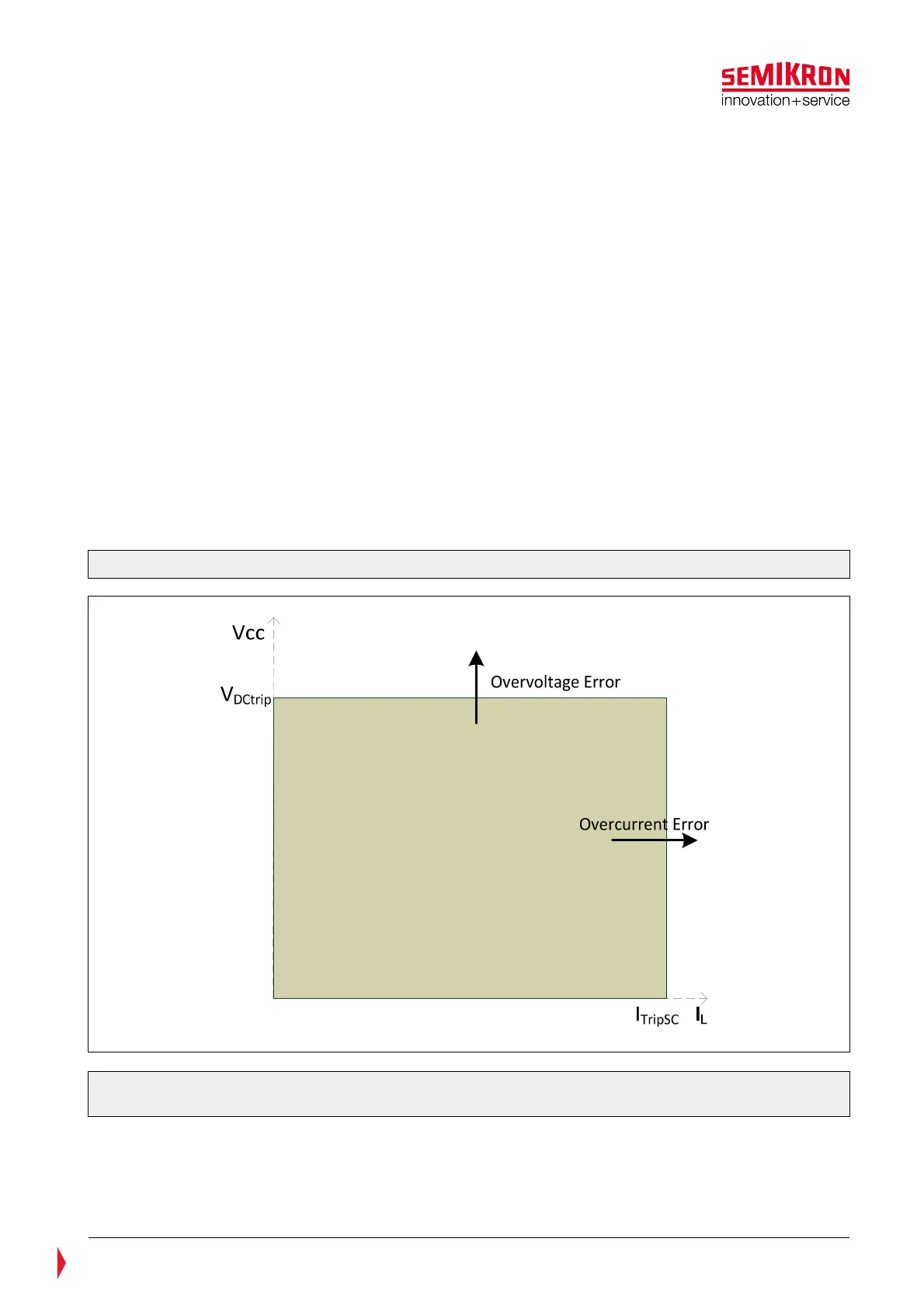
7.2 Safe Operating Area for SKiiP
®
4
The principle Safe Operating Area (SOA) for different SKiiP
®
4 systems is shown in the Figure 7.1. Please
refer to the corresponding data sheets for V
DCtrip
and I
TripSC
values for concrete SKiiP
®
4 types.
Figure 7.1: Safe Operating Area for standard SKiiP
®
4
Please note: The curves for Safe Operating Area (SOA) of 1500V photovoltaic SKiiP
®
4 Systems are
shown in the relevant data sheet and differ from this SOA.