© by SEMIKRON / 2017-09-07 / Technical Explanation / SKiiP
4
Page 36/73
5.3.7.3 Exceeding the maximum switching frequency
The maximum switching frequency is defined as f
sw
in the corresponding SKiiP
®
4 data sheet.
In order to prevent the module against overheating, the switching signal inputs HB_TOP and HB_BOT are
monitored with respect to oscillations. An error latch will be set if the switching frequency is higher than
twice the corresponding f
sw
.
Figure 5.20 illustrates the frequency ranges.
Figure 5.20: Switching frequency range
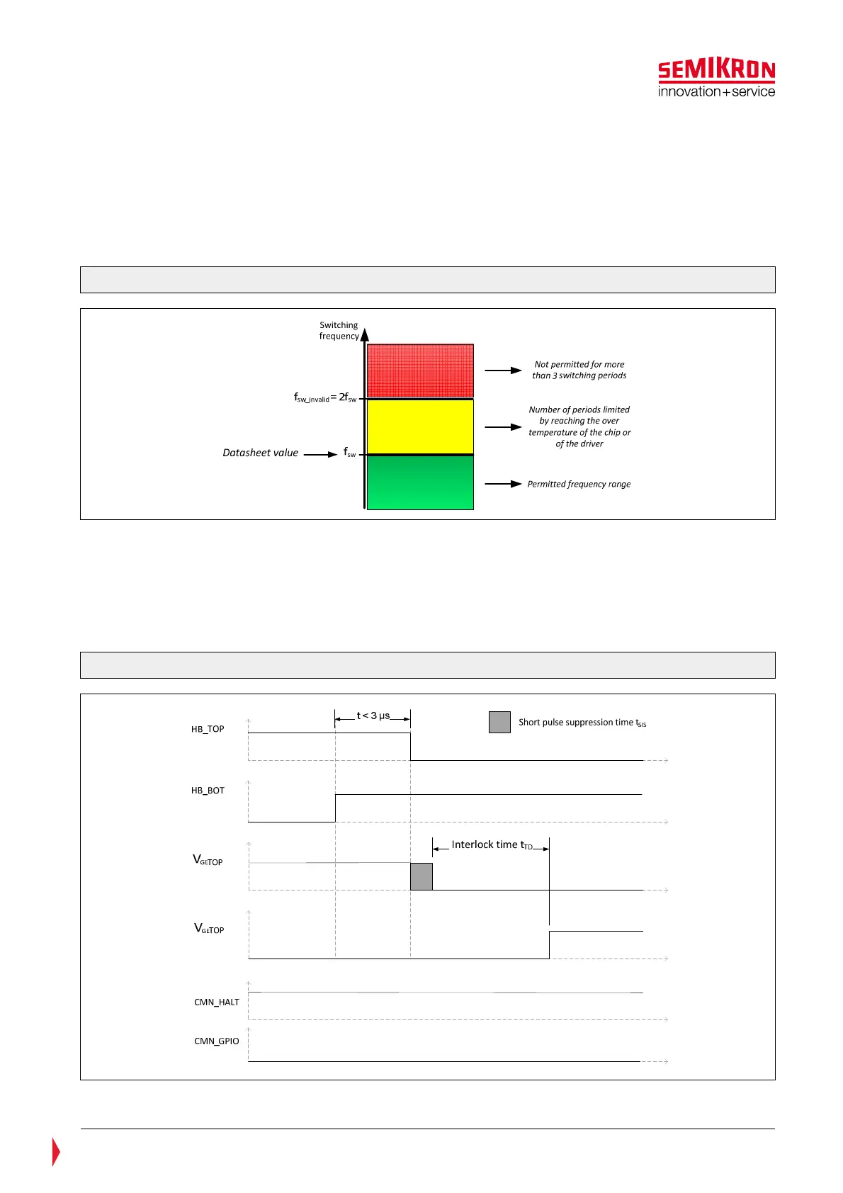
5.3.7.4 Overlapping of switching signals
It is not allowed, that TOP and BOT IGBT of a half bridge are turned-on at the same time. Such an
overlapping condition is observed and in case it persists for minimum
3µs the IGBTs are turned-off. After the overlapping situation has ended and the interlock time has elapsed
the opposite IGBT will be turned-on. The timing diagram of the error processing in case the overlapping
duration is shorter than 3µs, is shown in the Figure 5.21.
Figure 5.21: Timing diagram for the TOP/BOT overlapping error processing (t<3µs)