© by SEMIKRON / 2017-09-07 / Technical Explanation / SKiiP
4
Page 25/73
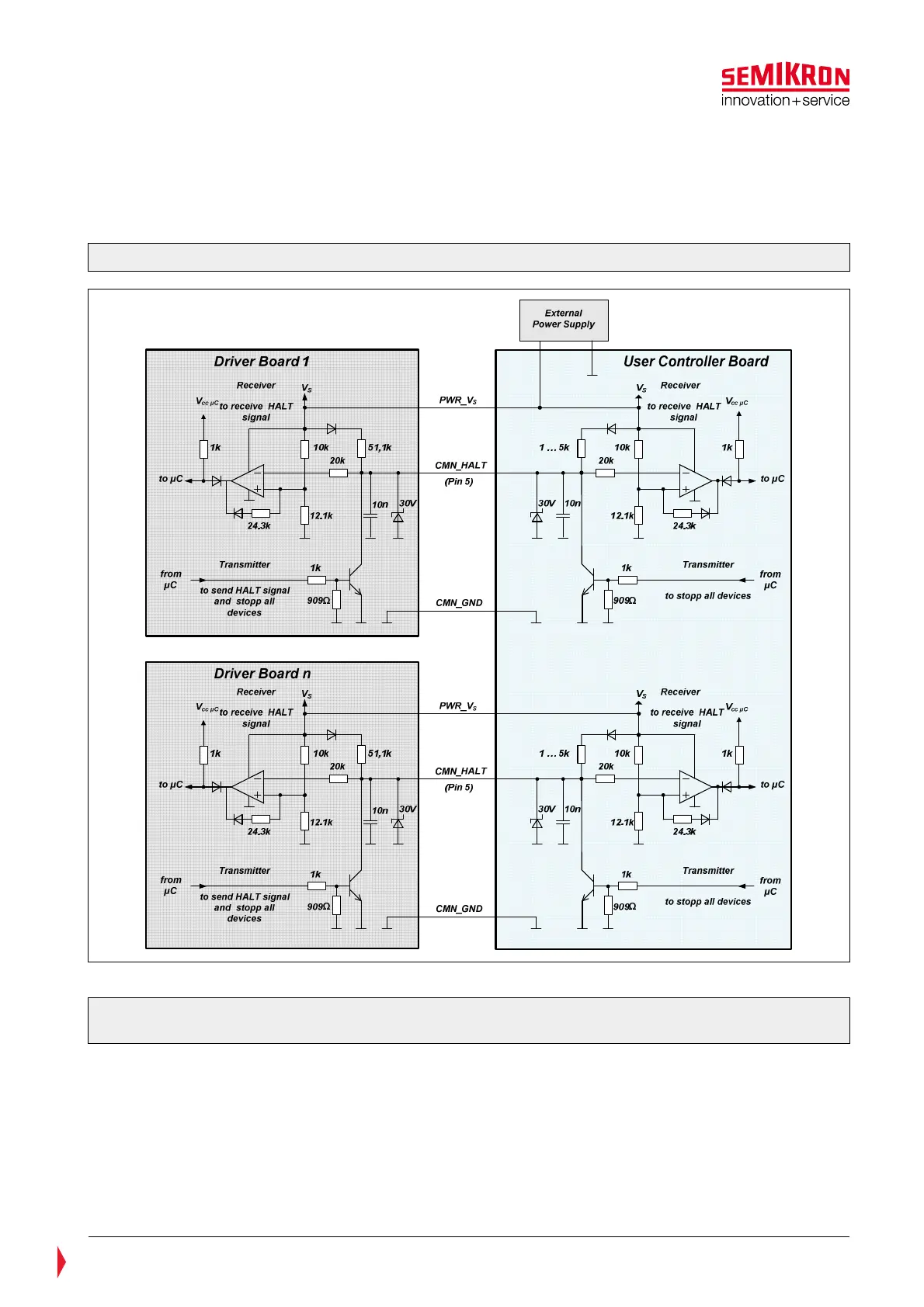
The HALT signal is pulled to GND by an integrated transistor. Pull up resistors are connected on each driver
board and on the user controller board. In order to keep the current low when several SKiiP units are
connected in parallel the pull up resistor on the driver board is relatively high (51,1kOhm). The pull up
resistor on the user controller board should be at least 1kOhm. A delay of the HALT signal due to the
capacitors on the driver board (10nF) must be considered.
Figure 5.9: Application example of the HALT signal processing for separated SKiiP
®
4 systems
Please note: If the HALT signal is not used it must be connected to the Vs pin according to Figure 5.16
(not used digital signals).