© by SEMIKRON / 2017-09-07 / Technical Explanation / SKiiP
4
Page 60/73
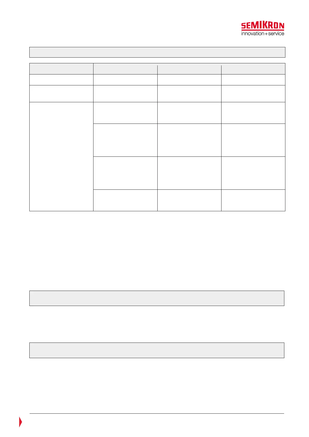
Table 7—2: Operation modes SKiiP
4 solar
Operation mode DC-voltage Load current Processing
Standard mode
V
DC
< V
DCtrip
I
Load
< I
trip
Hard Switch-off
Solar mode
V
DCtrip
< V
DC
< V
DCtripLL
I
Load
< I
LL
Switch off with IntelliOff
Error mode
I
Load
> I
trip
Switch off with
IntelliOff, over current
error indicated
V
DCtrip
< V
DC
< V
DCtripLL
I
Load
> I
LL
Switch off with
IntelliOff, solar mode
error indicated if
previous mode was
solar mode
V
DCtrip
< V
DC
< V
DCtripLL
I
Load
> I
LL
Switch off with
IntelliOff, over voltage
error indicated if
previous mode was
standard mode.
V
DC
> V
DCtripLL
Switch off with
IntelliOff, over voltage
error indicated
In case the SKiiP
®
4 is in solar mode (see Table 7—2) and at DC-Link voltage V
DC
> V
DCtrip
the load current
I
Load
exceeds I
LL
, the solar mode error will be indicated. In this case SKiiP
®
4 comes into error mode: the
SKiiP-driver sets the CMN_HALT-signal to LOW and the CMN_GPIO1-signal to HIGH. The interrupt of the
operation mode is released after the error memory reset time t
pRESET
has elapsed and the switching input
signals HB_TOP and HB_BOT are set to LOW.
The solar mode error can be read out by the available CANopen diagnostic software (GUI). In the case of
this error, both error bits 13 (over current) and 14 (DC-Link error) will be set. Please refer to the CANopen
Object Dictionary Rev.6 chapter 3.8. “Error recording” for more details.
Suitable snubber capacitors must be used in case the maximum blocking voltage V
CES
/V
RRM
is exceeded.
Please refer to chapter 7.6 for further information.
For safe operation the interlock time t
TD
is increased to a value 4,5µs in solar mode (Ref. diagram of Figure
7.13).
Please note: The load must be connected symmetrically and the load inductivity must be not less than
6µH.
The deactivation or change of the DC-Link trip level via CAN bus is not possible for the Solar SKiiP4.
The activation of the FRT-Function via CAN bus is possible (Please see CANopen Object Dictionary Rev.6).
7.9 Recommended temperature rating
Please note: The compliance to the temperature characteristics recommended in this chapter are
extremely important for the SKiiP
®
4 reliability and therefore for the long life time of the product.
The indicated failure rate describes the probability of the occurrence of a failure within a certain time span.
Usually, the failure rate follows a so-called bathtub curve, shown in Figure 7.14: High in the beginning
(failures known as early failures), then dropping to a low and more or less constant value (the random
failures) before it rises again as wear-out begins to set in and end-of-life failures set a limit to the useful
life of a component.