© by SEMIKRON / 2017-09-07 / Technical Explanation / SKiiP
4
Page 23/73
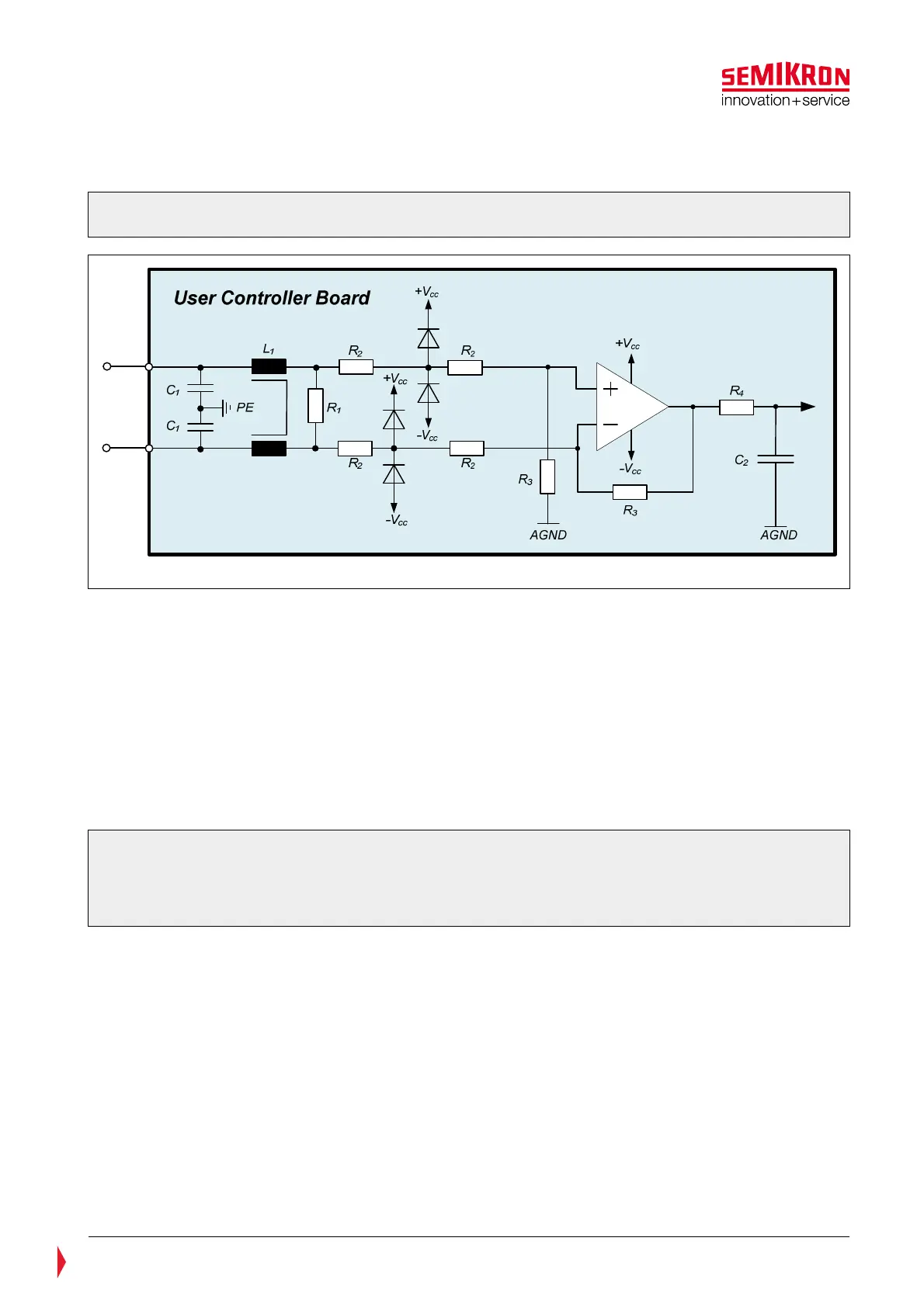
A description of the equivalent analogue input circuit relevant to the user’s controller board is shown in
Figure 5.8.
Figure 5.8: Application example – symmetric wired differential amplifier. Terminal
description HB_I and HB_I_GND for current measurement
The recommended values below have to be checked in the application.
• The equivalent input capacitance should not be higher than 1nF for current measurement and 10nF for
temperature and voltage measurement to achieve stable operation of the amplifier circuit on the
SKiiP
®
4 board. Its signal response has to be checked in combination with the used signal cable.
• C1 leaks differential and common mode high-frequency interference currents. This capacitor reduces the
bandwidth of the analogue signal. This can lead to control problems like AC current harmonics.
Depending on the application PE should be connected to an appropriate ground, e.g. chassis ground.
• Common Mode Choke L1 is used for filtering of common mode currents. The current-compensated ring
core choke with ferrite core and rating 51µH/0,5A is recommended.
• Resistor (R1). The interference sensitivity of the overall circuit (user control, driver) is reduced by a
continuous current flow through this resistor. Recommended value: 10kOhm
Please note: Capacitors should not be used in parallel to the feedback resistor (R3) and also not to the
resistor of the non-inverting input to ground (R3). These capacitors have often high tolerances, so the
common-mode rejection of the circuitry is reduced by this effect. No capacitor should be connected
between the plus- and the minus-pin of the operational amplifier as well. This additional corner
frequency can lead to an oscillating signal.
• The input resistor (R2) should be split and installed between the clamping diodes. The current through
the diodes is limited by this resistor. A diode with a low reverse current should be selected e.g. BAV99.
• To achieve a good noise performance a low-impedance feedback resistor should be used (R3).
Recommended value: 25kOhm.
• A low pass filtering stage should be implemented to avoid remaining differential interferences. It can be
realized by a simple R-C network (R4, C4) at the end of operational amplifier. The corner frequency of
the filter should be adjusted to the behaviour of the operational amplifier used and the necessary
bandwidth of the analogue signal (Temp/DC-Link/Current).
• A Rail-to-Rail amplifier is recommended for better performance. If not available the OPAMP’s negative
supply terminal shall be connected –VCC, e.g. to negative voltage instead of ground in order to use the
complete voltage range of the amplifier, especially close to 0V. The possible negative output voltage of
the amplifier has to be considered when designing the interface circuit.
• AGND should be connected to the ground of the analogue signal processing at the user controller board.