© by SEMIKRON / 2017-09-07 / Technical Explanation / SKiiP
4
Page 26/73
5.2.7 CMN_GPIO1 signal
The CMN_GPIO1 signal is available at Pin 18 of the SKiFace interface.
The CMN_GPIO1 signal is the inverted HALT signal (
) that can be used as error output signal of the
SKiiP
®
4 (in case of activated FRT-function please refer to chapter 7.7 for further information).
Please note: As the CMN_GPIO1 signal is the inverted HALT signal, there is no possibility to see which
SKiiP
®
4 has set the error output signal. For this purpose the CAN-diagnostic interface should be used
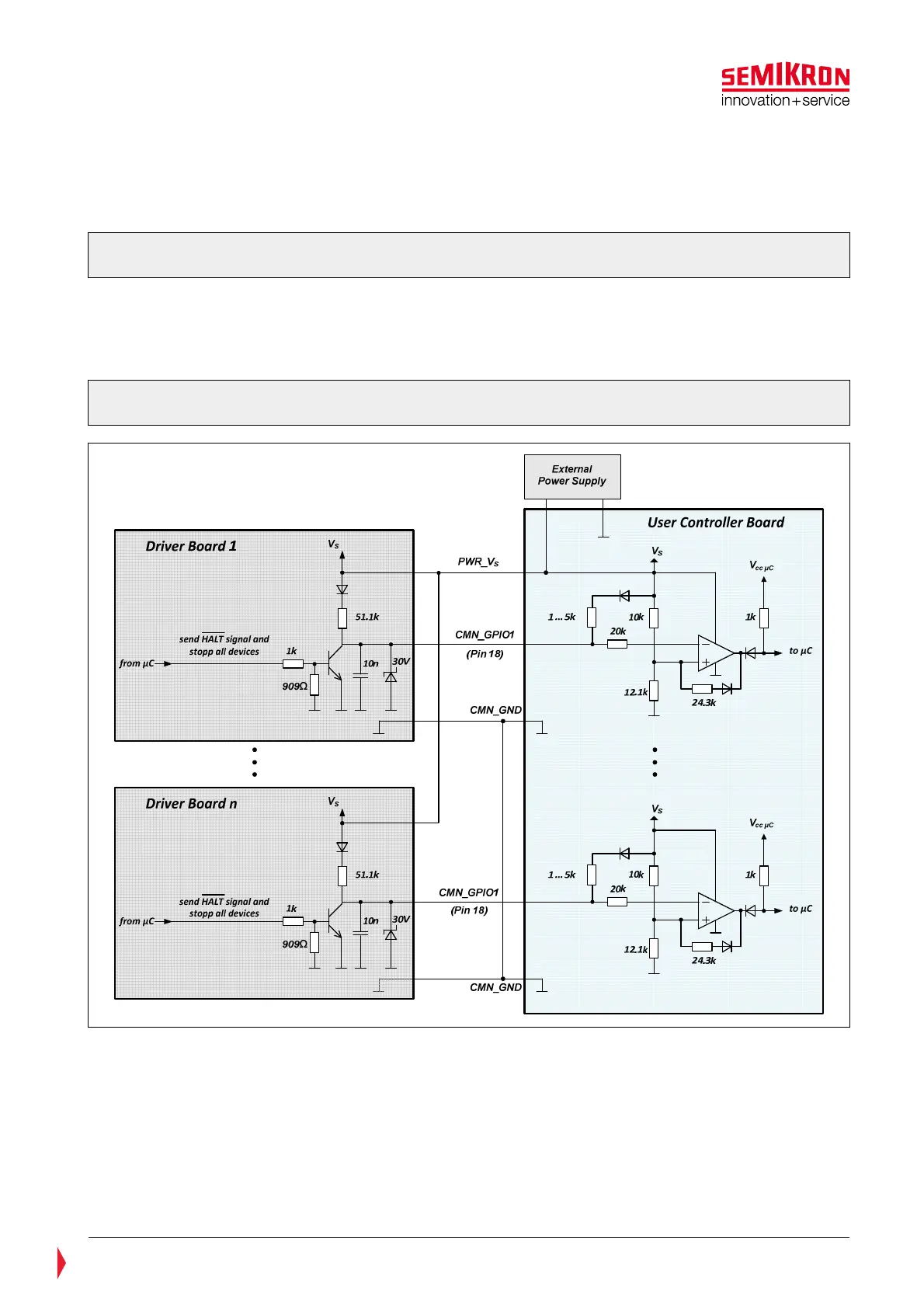
Figure 5.10 indicates:
• on the left hand side the output stage of the CMN_GPIO1 signal
• on the right hand side an example of the input stage of the user controller board for each
CMN_GPIO1 output of several SKiiP
®
4
Figure 5.10: Application example of the CMN_GPIO1 (inverted HALT signal) as error output
signal