© by SEMIKRON / 2017-09-07 / Technical Explanation / SKiiP
4
Page 57/73
Figure 7.9: Graphic schematic of the wind mill
When doubly fed induction generators are used only the rotor current is controlled by the converter.
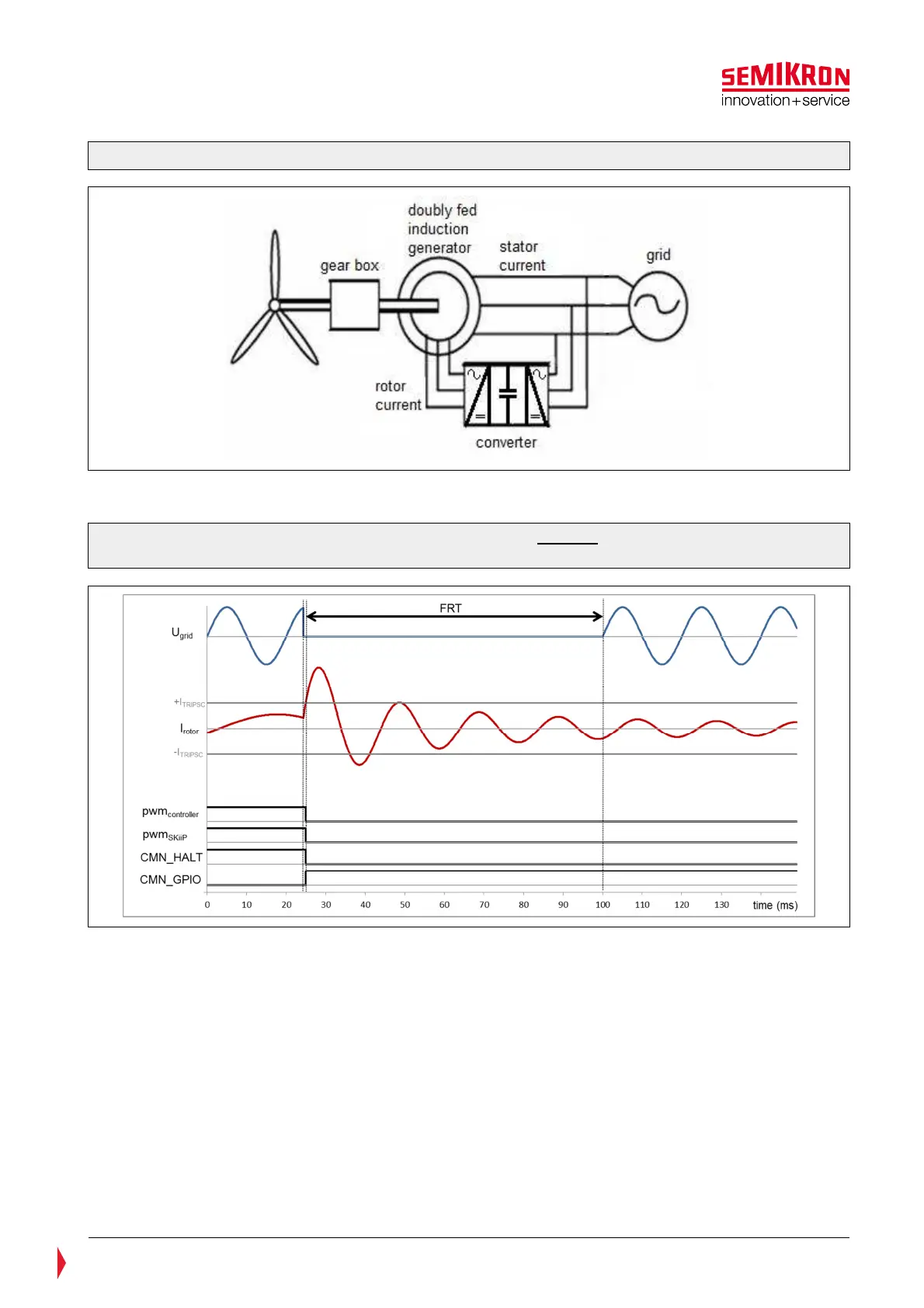
Figure 7.10: Graphic presentation of SKiiP
®
4 behaviour without FRT-function activated in
case of overcurrent
In case of an FRT or LVRT the rotor current can increase to levels higher than the overcurrent trip level of
the SKiiP (I
TRIPSC
) and the SKiiP will trip. Consequentially the PWM of the IGBTs (pwm
SKiiP
) is interrupted by
the SKiiP-driver itself regardless of whether the PWM from the customer controller (pwm
controller
) is running.
The SKiiP-driver sets the CMN_HALT-signal to LOW and the CMN_GPIO1-signal to HIGH. The interrupt of
the pwm
SKiiP
is released after the error memory reset time t
pRESET
has elapsed and if the switching input
signals HB_TOP and HB_BOT are set to LOW. In most cases t
pRESET
is too high to fulfill the grid code
requirements.
If the FRT-function is activated the error-handling of the SKiiP will be changed and the grid code
requirements can be fulfilled. In this case CMN_GPIO1 will not be the inverted CMN_HALT signal anymore.
An overcurrent trip will never set CMN_HALT to LOW and it is never stored in the SKiiP error memory.