© by SEMIKRON / 2017-09-07 / Technical Explanation / SKiiP
4
Page 62/73
of the DCB-sensor temperature (available at the driver connector as analogue voltage signal) can
provide a first indication that the system operates as simulated.
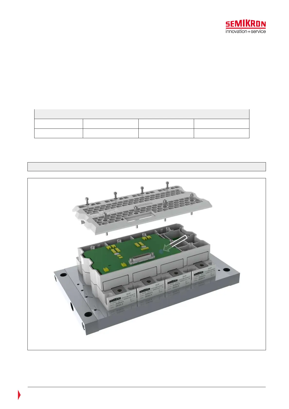
• Gate driver: Although the gate drive circuit can operate at ambient temperatures of up to T
a
= 85°C, it
is recommended that the average ambient temperature of the driver board usually does not exceed
40°C. Lowering the gate driver temperature can be achieved by an additional air forced cooling of the
SKiiP’s housing. The actual temperature of the gate driver T
driver
in situ could be measured by means of
a temperature sensor located at the bottom side of the driver PCB (see Figure 7.16). The value of the
sensor could be read out via CAN-bus interface (please refer to the CANopen documentation for further
information). If the temperature exceeds the T
Driver Trip
given in the SKiiP
®
4’s data sheet the switching
operation will be blocked and an error signal will be issued correspondingly. The default values for the
T
Driver Trip
are provided in Table 7—3: Default values for the T
Driver Trip
Table 7—3.
Table 7—3: Default values for the T
Min. Value Typ. Value Max. Value
T
113 115 124
If necessary the trip level of the temperature sensor can be adjusted to a lower level by the CAN-bus
interface.
Figure 7.16: Position of the driver temperature sensor SKiiP4