© by SEMIKRON / 2017-09-07 / Technical Explanation / SKiiP
4
Page 64/73
Figure 7.17: An example of SKiiP
®
4 AC terminal parallel connection
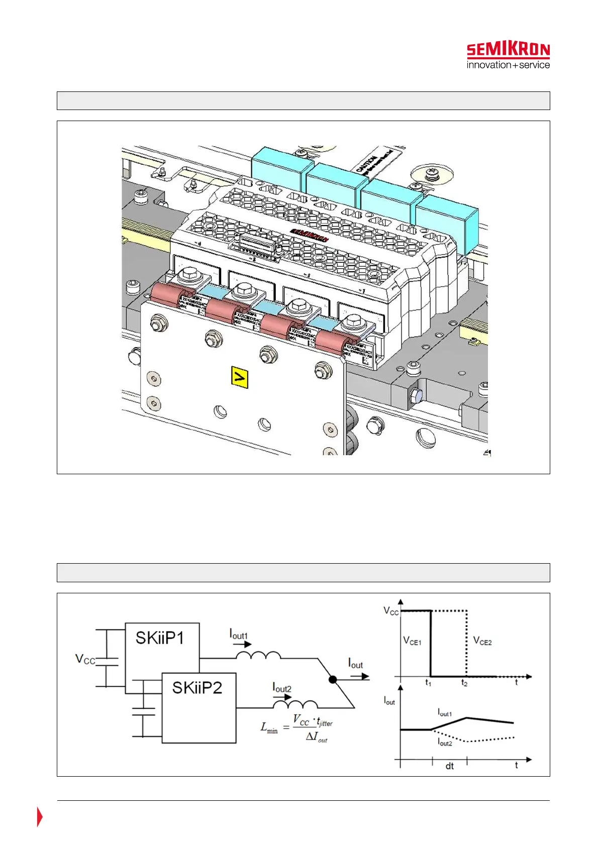
To minimize the above mentioned effects the system designer has to make sure, that there is sufficient
inductance between the AC output terminals of the paralleled SKiiP subsystems. The impedance has two
tasks:
• On one hand it should prevent from the generation of an imbalance current during the switching
moment. That could lead to different switching loss and in severe cases to undesired oscillations.
This is shown in Figure 7.18. The value t
jitter
is given in the SKiiP
®
4 data sheet on page 2.
Figure 7.18: Effects of paralleling SKiiP
®
4