© by SEMIKRON / 2017-09-07 / Technical Explanation / SKiiP
4
Page 22/73
5.2.5 Analogue Output Signals
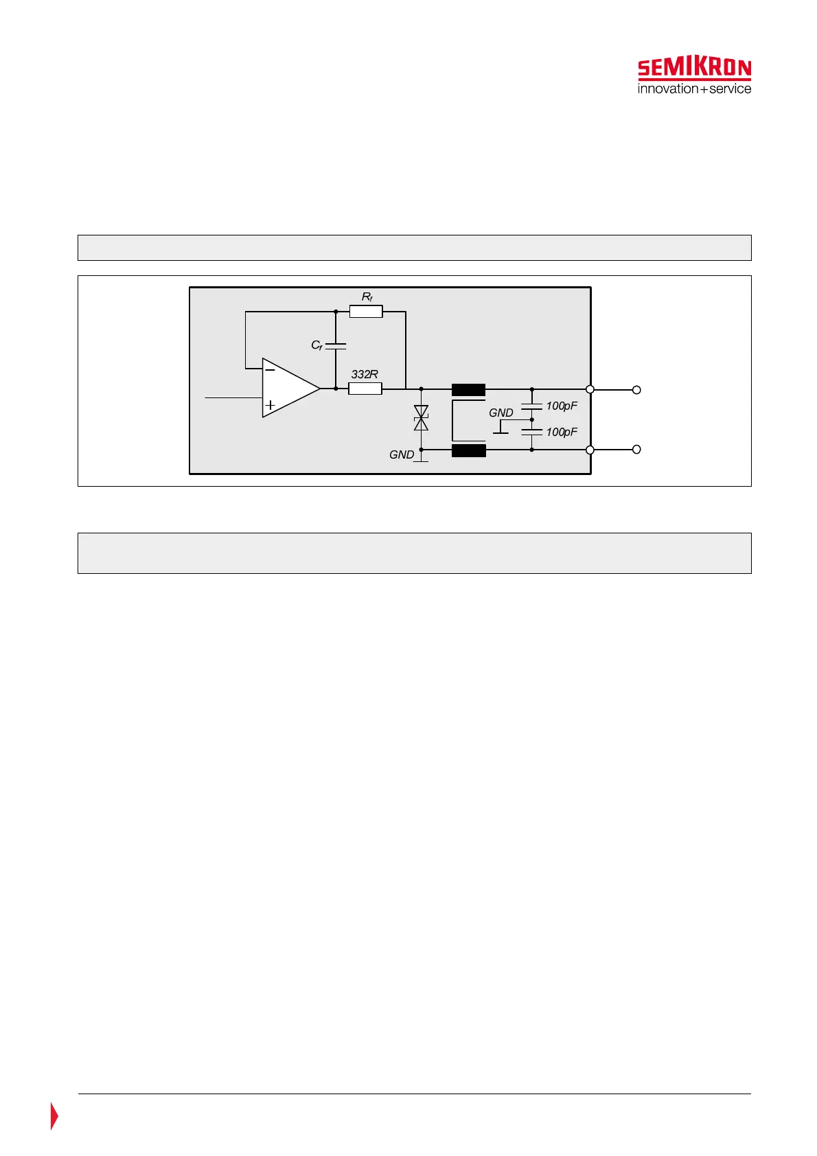
The schematic in the Figure 5.7 shows the analogue output circuit of the gate driver.
This circuit is utilized in:
• Measurement of AC-current
• Measurement of DC-link voltage
• Measurement of DCB-sensor temperature
Figure 5.7: Schematic view of the analogue output signals
A resistor avoids damages potentially being caused by a temporary short circuit at the analogue output.
Please ensure that the maximum current driven by the output of the operational amplifier
does not exceed 5mA.
A common mode choke and 100pF capacitors are used on the outputs to obtain high noise immunity.
On the user controller board a differential amplifier should be used which is connected to the analogue
output and the corresponding ground signals (CMN_TEMP_GND, CMN_DCL_GND, HB_I_GND). This ensures
accurate measurement of the analogue signals because there is no voltage drop on the analogue ground
wires due to the high input impedance of the differential amplifier (refer to Figure 5.13).