© by SEMIKRON / 2017-09-07 / Technical Explanation / SKiiP
4
Page 58/73
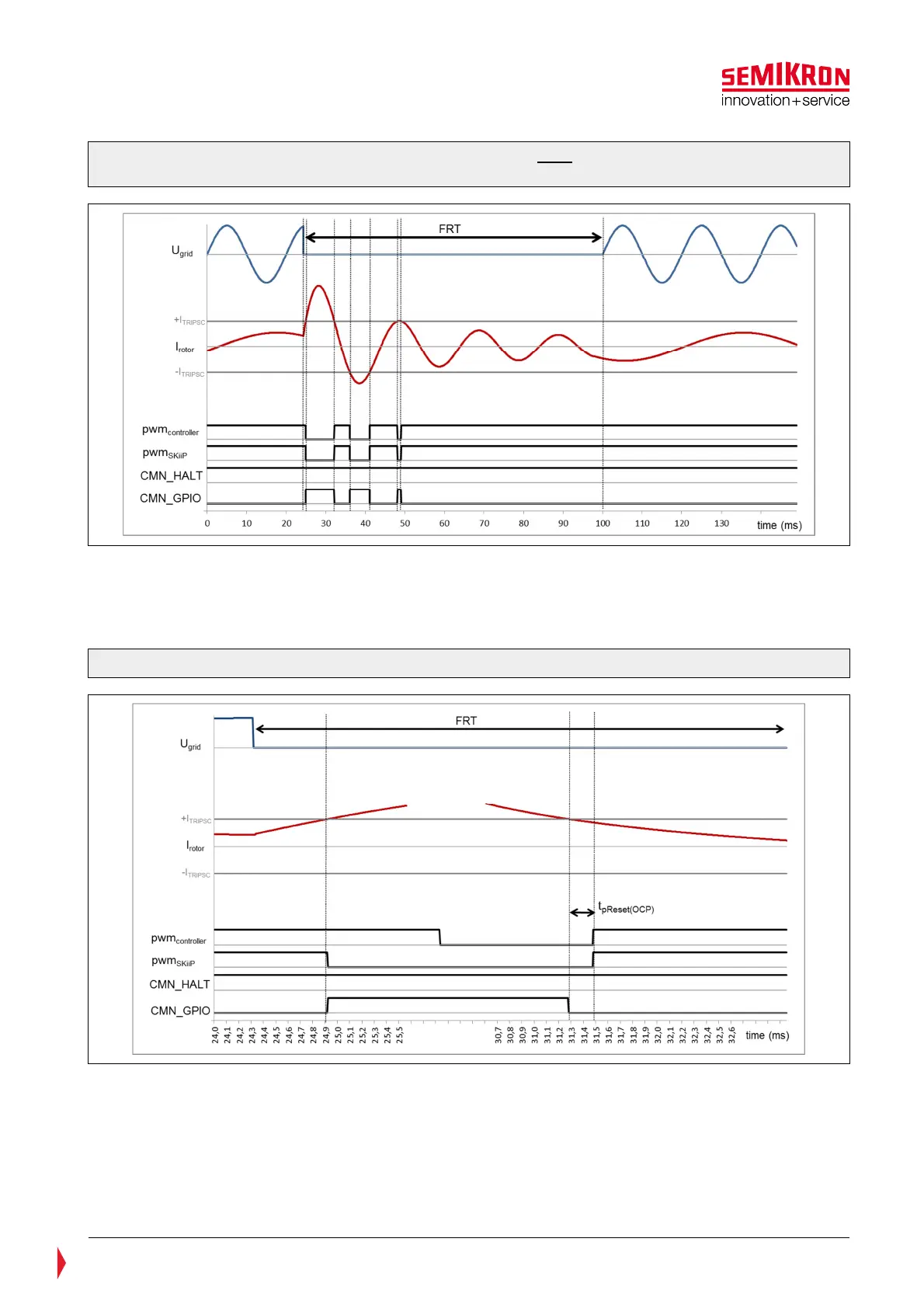
Figure 7.11: Graphic presentation of SKiiP
®
4 behaviour with FRT-function activated in case of
overcurrent
If the rotor current I
rotor
exceeds the level I
TRIPSC
the SKiiP-driver will interrupt the pwm
SKiiP
and will set the
signal CMN_GPIO1 to HIGH as long as I
TRIPSC
is exceeded. The pwm
controller
must be turned off. After a
period t
pReset(OCP)
of 200µs which starts after I
rotor
is below I
TRIPSC
and pwm
controller
is turned off, the SKiiP is
enabled to start switching as long as the overcurrent trip level is not exceeded again.
Figure 7.12: Graphic presentation of the driver processing in FRT-case
The freewheeling diodes conduct the rotor current I
rotor
during the period of blocked pwm
SKiiP
. The user
must take care that the diodes will not be overloaded thermally, because the SKiiP’s overcurrent protection
is deactivated and the thermal protection is not able to protect the diodes in this FRT operation. Thermal
calculations or simulations are necessary to confirm that the SKiiP diodes will not be overloaded.
The FRT-Function can be activated through the CAN-Bus interface. Please refer to the CAN user’s manual
documentation for further details.