© by SEMIKRON / 2017-09-07 / Technical Explanation / SKiiP
4
Page 59/73
7.8 Solar function
For an operation of the SKiiP
®
4 during the startup phase typically in PV-solar applications, a higher DC-link
voltage trip level must be available for low load currents in contrast to standard applications. A special
modification of the current SKiiP
®
4 1700V type has been carried out to fulfill this specific requirement of
the PV-solar market.
Please note: The solar function cannot be activated through CAN and, hence, a dedicated SKiiP
®
4 for
such PV-solar specific operation must be ordered.
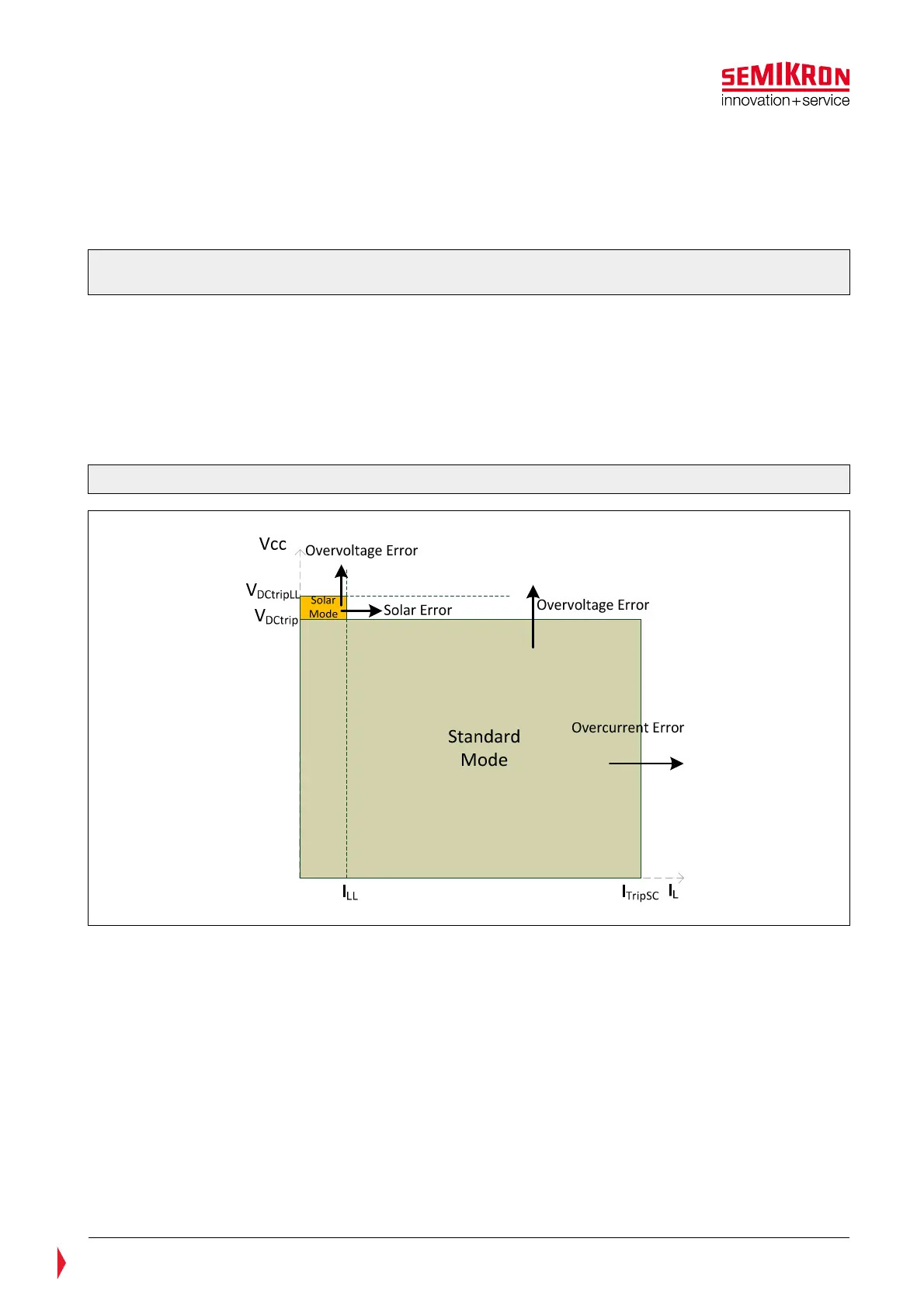
The Safe Operating Area (SOA) diagram of the PV SKiiP
®
4 is indicated in the Figure 7.13. While the SOA
for the standard SKiiP
®
4 (shown in the Figure 7.1) is limited by the over voltage trip level V
DCtrip
and over
current trip level I
TRIPSC
, the modified SOA of the PV SKiiP
®
4 employs an extended area above V
DCtrip
and
limited by the low load current I
LL
and a higher over voltage trip level V
DCtripLL
. This operation mode is called
“solar mode” and is marked orange in the right diagram of Figure 7.13. Parameters I
LL
and V
DCtripLL
are
given in the data sheets SKiiP
®
4 Solar. The operation at DC-link voltages higher than the recommended
voltage levels and especially in this “solar mode” extended SOA is very time limited since the probability of
a cosmic ray induced fault increases exponentially under such conditions.
Figure 7.13: SOA for SKiiP
®
4 Solar
The operation modes for SKiiP
®
4 solar are listed in the Table 7—2.