© by SEMIKRON / 2017-09-07 / Technical Explanation / SKiiP
4
Page 30/73
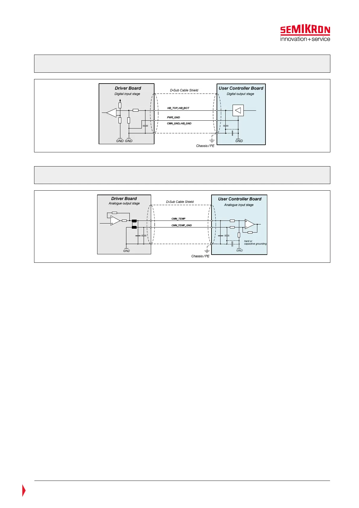
Figure 5.14: Ground and shield connection. Principle schematics for Ground and shield
connection. Principle equivalent circuit of switching signal inputs
Figure 5.15: Ground and shield connection. Principle equivalent circuit for analogue output
signals (Example: Temperature output)
5.2.11 Reserved or not used signals
Unused pins of digital signals (CMN_GPIO1, CMN_GPIO2) at the user controller board should be connected
to V
S
by a 51kOhm resistor in series to a diode as shown in Figure 5.16.
The diode prevents from supplying the controller from the driver board when the controller is not supplied.
Also a capacitor should be connected to GND to damp burst signals.
For the CAN interface it is recommended to connect the CAN open signals by 121 Ohm resistor, in case the
CAN interface will not be used.
Unused analogue signals should be connected to GND by a 10kOhm resistor.