© by SEMIKRON / 2017-09-07 / Technical Explanation / SKiiP
4
Page 35/73
5.3.7 Error Management
A failure caused by
• Under voltage of the primary side (refer to chapter 0)
• Exceeding maximum switching frequency (refer to chapter 5.3.7.3)
• Overlapping of TOP/BOT switching signals (refer to chapter 5.3.7.4)
• Internal bridge short circuit (refer to chapter 5.3.7.5)
• Exceeding maximum DCB-sensor/driver temperature
• DC-link overvoltage
• Load overcurrent (OCP)
• Internal driver error
will set the HALT signal to LOW state (indicating that the SKiiP4 is not ready to operate) as long as the
error is present, or at least for the “error memory reset time”, t
pRESET
(refer to SKiiP
®
4 data sheet, page 2).
The IGBTs will be turned-off and switching pulses from the controller won´t be transferred to the output
stage. During this time the driver will check if the switching input signals HB_TOP and HB_BOT are set to
LOW. If this is the case and no error is present anymore the driver will release the HALT signal. If the input
signals have not been switched to LOW state the driver will pull the HALT signal to LOW (dominate) as long
as the switching input signals HB_TOP and HB_BOT are not LOW. So in case of error the switching input
signals HB_TOP and HB_BOT should be set to LOW within the error memory reset time t
pRESET
and not be
activated before the HALT signal is in HIGH state again (see Figure 5.22).
Please note: The DC-link overvoltage monitoring is disabled at 1500V Photovoltaic SKiiP
®
4 Systems
5.3.7.1 Error delay time, t
d(err)
The error delay time is the propagation delay time of an error. This time is different for the different types
of errors. The precise values for each specific error type can is summarized in Table 5—6
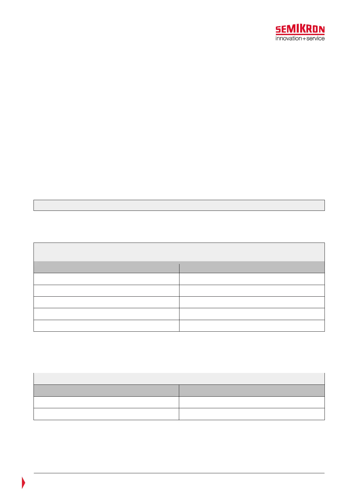
Table 5—6: Error delay time
Type of error Typical values
DC-Link overvoltage 160 µs
Overcurrent protection (OCP-error) 2 µs
Short circuit protection (SCP) by V
monitoring 3 µs
DCB-sensor over-temperature 6 ms
Exceeding maximum switching frequency 6 µs
*
35ms for SKiiP®4 with part nr. 20601xxx
5.3.7.2 Under Voltage Protection (UVP) supply voltage
The gate drive board is equipped with an under voltage protection of the supply voltage. The UVP of the
primary side monitors the supply voltage V
s
. Table 5—7 indicates the trip level.
Table 5—7: Signal characteristics of Under Voltage protection of the primary side
Signal Characteristics Typical values
Undervoltage protection trip level 18,0V
Threshold level to reset after the failure event 18,5V
If the supply voltage of the driver board drops below the
trip level, the IGBTs will be turned off. The switching input signals HB_TOP and HB_BOT will be ignored and
the status signal HALT is set to LOW state. The system will restart after the error memory reset time t
pRESET
(refer to SKiiP
®
4 data sheet, page 2), if the supply voltage exceeds the reset threshold level after the
failure reason has disappeared and if the switching input signals HB_TOP and HB_BOT are set to LOW.