1.9
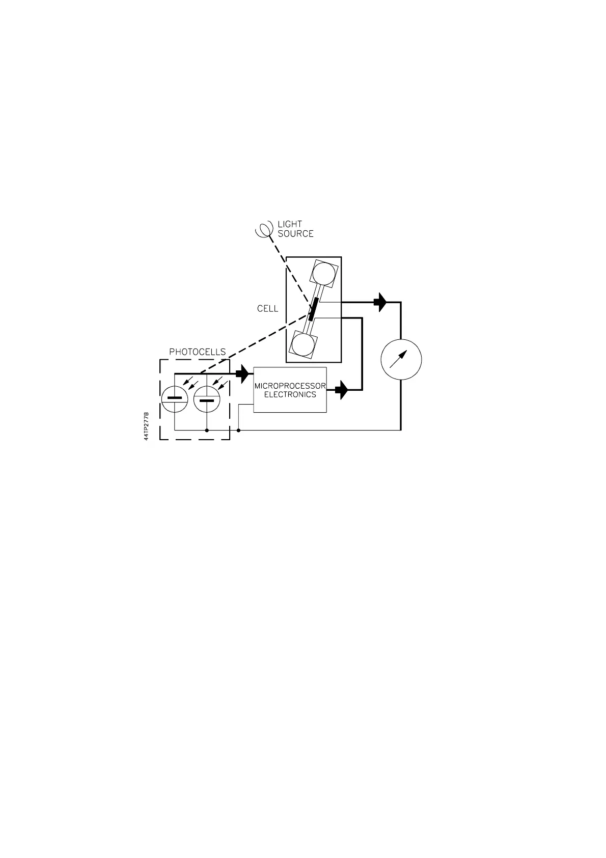
Figure 1.4 Analyser Schematic
A single turn of fine platinum wire (the feedback coil) is secured in place around the dumb-bell.
A rugged, taut band platinum ribbon suspension attached to the midpoint of the dumb-bell
positions the dumb-bell in the strong non-uniform magnetic field existing between the specially
shaped pole pieces of the permanent magnet structure. See Figure 1.3.
The angular position of the dumb-bell is sensed by a light beam projected onto a mirror
attached to the dumb-bell from which it is reflected onto a pair of photocells. See Figure 1.4.
The difference in the output from these photocells is fed to an amplifier.
When a sample gas containing oxygen surrounds the dumb-bell, the oxygen molecules are
attracted to the strongest part of the magnetic field, thus enhancing the magnetic field around
the dumb-bell. This changes the force acting on the dumb-bell causing a displacement of the
light beam across the photocells, which in turn results in a difference signal being sensed by
the amplifier. The resulting output of the amplifier is a current, proportional to the oxygen
content of the sample, which is fed to the feedback coil of the measuring cell. This produces a
magnetic field which opposes the forces causing the dumb-bell to rotate. Thus the dumb-bell is
maintained in its original position.
Since this current is proportional to the oxygen content of the gas sample it is used to develop
the output signal from the analyser. This current feedback force balance design is resistant to
mechanical shock and has outstanding accuracy and linearity.
See Section 1.7.5 for measuring cell options.