4.6
4.4 SAMPLING SYSTEM MAINTENANCE
If a Servomex sampling system 1161 or 1162 is used refer to Section 5.4.
4.5 BATTERY REPLACEMENT
This is only required on earlier analysers
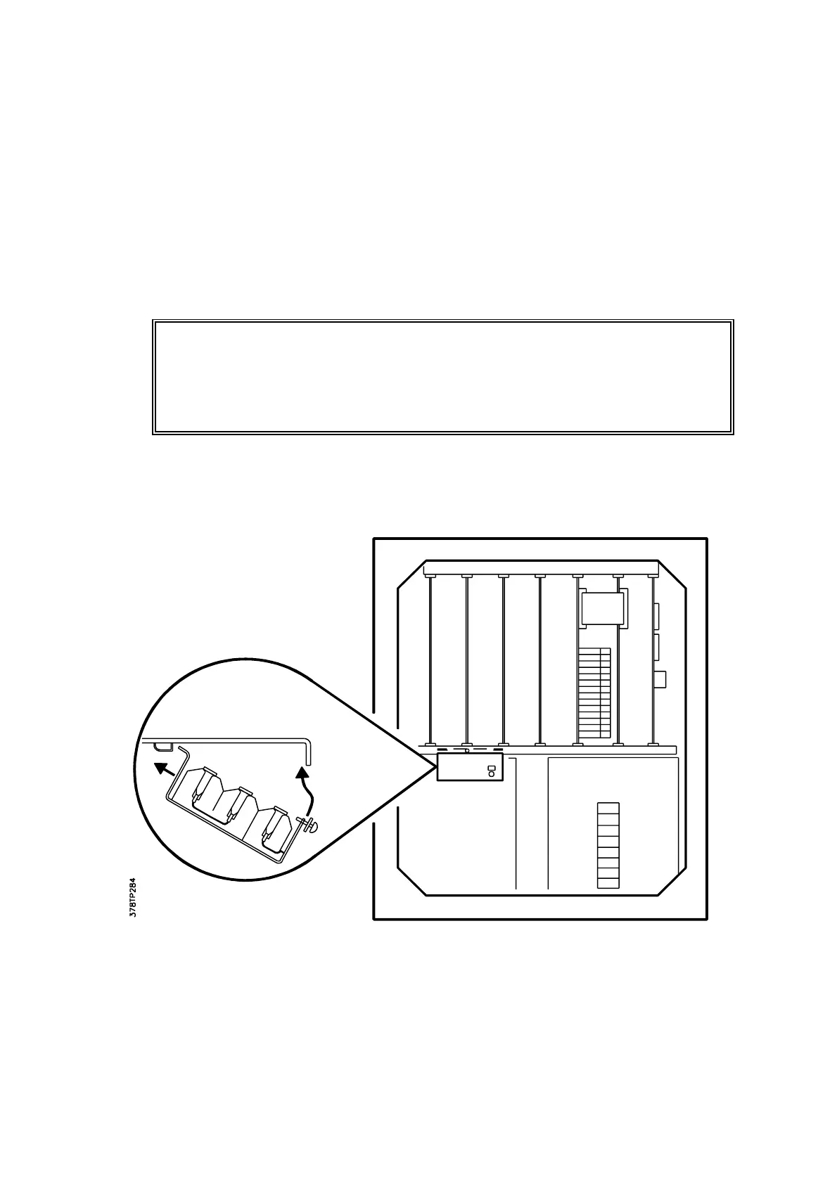
Batteries are located in the Control unit except for maximum separation systems when they are
in the Interface unit.
WARNING
This procedure must not be performed in a hazardous area.
NOTE: Always ensure that the analyser remains ON when replacing batteries.
Failure to do this will result in the memory being totally lost from the microprocessor unit.
Figure 4.1 Location of Memory Batteries
To renew the back-up batteries proceed as follows:
1. Open the front panel of the Control (or Interface) unit by removing the four 6mm socket
head screws.