2.28
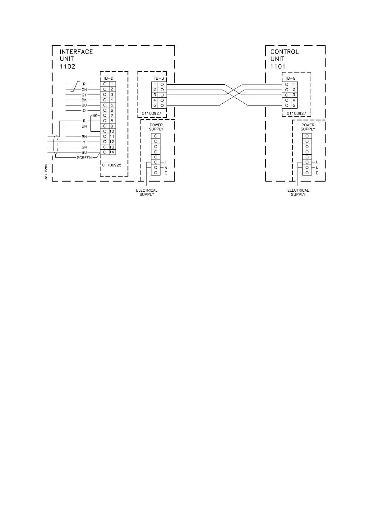
Figure 2.11 Interface to Control Unit Connections
Figure 2.11 shows the connections between the Interface and Control units (analyser Codes
03, 23, 06, 16 and 26).
See Section 2.11.2 if the 01100 927 boards have not already been fitted.
2.10 CABLE KIT OPTIONS
A cable kit is available for the signal and heater cables. The kit contains cable glands. Cable
length should be specified up to a maximum of 100m. The signal cable meets the
requirements detailed in Section 2.8.1.
Part Numbers are: 01100 995 (gland kit)
1566-8741 (signal cable)
1566-8215 (heater cable)
1. The signal cable option is seven twisted pairs of 16/0.2 mm (20 AWG) conductors,
blue polythene insulated, with an overall shield and drain wire and an external
polythene sheath and generally conforms to BS 5308 Pt.1 and is suitable for
connecting intrinsically safe circuits. In hazardous areas it should be installed to
comply with relevant certification conditions and local regulations. It complies with the
electrical characteristics specified in the British, CENELEC and C.S.A. certification.
2. The heater cable option is a three-core pvc insulated,16/0.2 mm (20 AWG) conductor
size with a pvc sheath.