2.25
2.8.1.4 C.S.A. Certification Requirements
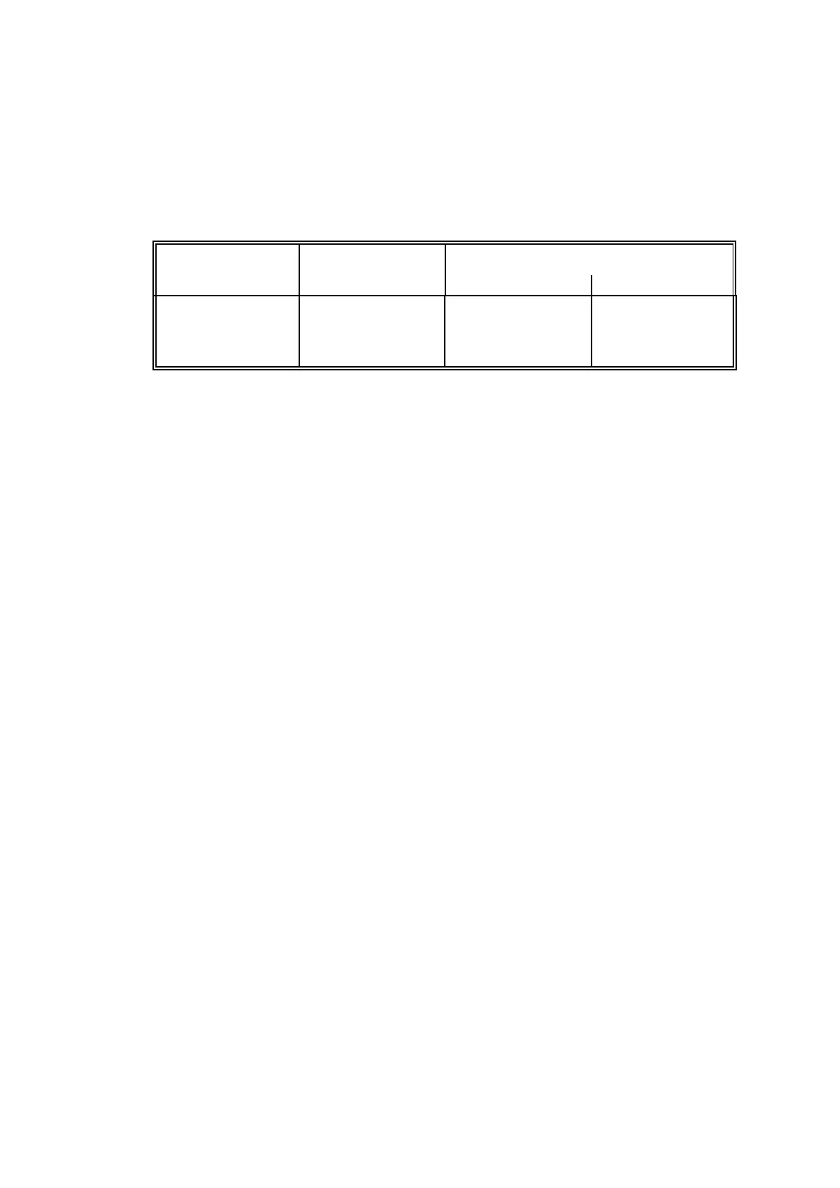
Capacitance and inductance or inductance to resistance (L/R) ratio for this cable must not exceed
the following values:
For O
2
not exceeding 21%
Gas group Capacitance Inductance or L/R ratio
: F mH : H/ohm
B
C
D
0.35
1.05
2.8
2.5
7.5
20.0
64
192
512
Installation of this cable should conform to CSA STD. C22.2 No. 157 M1987: Clause 4.3.8.9.
See certification details in Supplementary manual 01100 008A for conditions of use, in
particular system wiring schematic 01100/898 CSA.
See Figure 2.8(a) for installation details of this cable to the Control (or Interface unit). The
cable must enter the Control unit by the gland hole in the top of the unit and be retained by the
metal cable shield. The cable screens are terminated to the earth (ground) lug on the gland
locknut.
2.8.2 Heater Cable
The heater cable carries power to the Transducer unit heaters. It terminates in the terminal
box at the Transducer unit and at the power supply unit of the Control or Interface unit. Cable
requirements are:
1. 3-Core (L.N.E.)
2. Voltage rating suitable for 220V a.c. nominal
3. Current rating not less than 1A (heater fuse rating).
4. Conductor cross sectional area to be within the range 0.5 to 2.5 mm
2
. (20 to
14 AWG) and the loop resistance to be less than 2.5 ohms.
5. For hazardous area applications the cable should be of a type suitable for the
classification of the area and correctly installed. See certification details in
Supplementary manual 01100 008A for conditions of use.
Where the heater cable is likely to pick-up high levels of interference from adjacent cables and
equipment it is recommended that a shielded cable is used and grounded at the Control or
Interface unit.
See Figure 2.9 for connections to the 1131 Transducer unit (analyser Codes 02 and 22) and
Figure 2.10 for the 1132 and 1133 Transducer unit (analyser Codes 04, 14, 24, 06, 16 and 26).