2.26
2.9 INTERFACE TO CONTROL UNIT INTERCONNECTIONS
The Interface and Control units have to be connected by a cable carrying digital signals. This is
terminated in both units on the Data Output board (01100 927). Cable requirements are:
1. Two twisted pairs with an overall shield or screen and drain wire.
2. The recommended conductor size is 16/0.2 mm (20 AWG), but others are
acceptable provided the cross-sectional area of the conductor is within the
range 0.5 to 1.5mm
2
(20 to 16 AWG) and the loop resistance does not exceed
50 ohms.
Note: The loop resistance of 500m of 16/0.2 mm(20AWG) cable is
approximately 40 ohms.
3. For hazardous area applications the cable should be of a type suitable for the
classification of the area and correctly installed. See certification details in
Supplementary manual 01100 008A for conditions of use.
4. The maximum length of the cable is 500m.
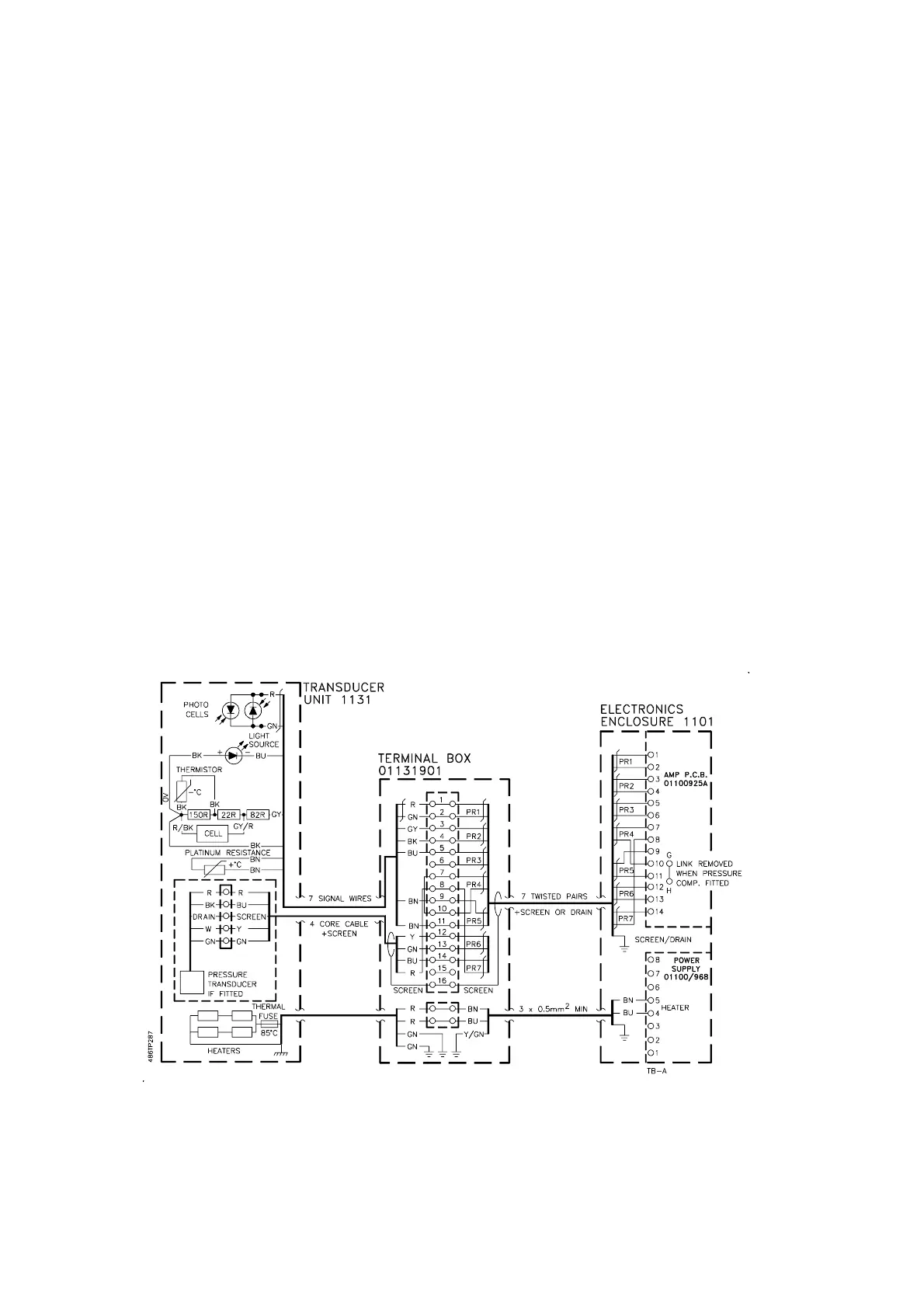
Figure 2.9 Connections to 1131 Transducer Unit
Architecture Code 02 and 22