2.31
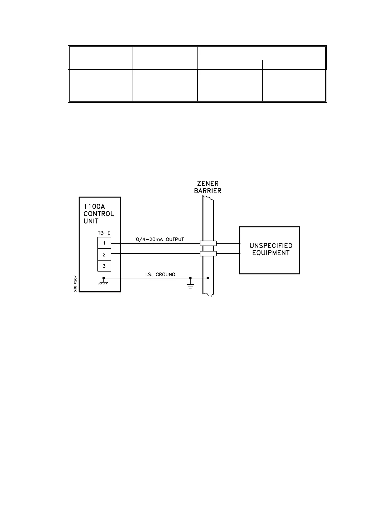
Figure 2.13 Analogue Output - Hazardous Area Applications With Output
Board 01100929
Gas group Capacitance Inductance or L/R ratio
: F mH : H/ohm
IIC
IIB
IIA
0.2
0.6
1.66
1.9
5.7
16.2
45
135
360
2.11.1.3 Output With Board 01100 929
This board was fitted to earlier analysers and may be identified by having three brown output
terminals, TB-E.
The output can be either isolated or connected to ground at the analyser. In hazardous
applications it must always be grounded.
The analogue output is certified intrinsically safe (ib) and, when the 1100A is used for
hazardous applications, certification conditions place certain restrictions on the way the output
may be connected. The certificates give full details (See Supplementary manual, part no.
01100008A). Unless the output is being connected to an intrinsically safe indicator then, in
general, it will be necessary to fit zener barriers. A typical example is shown in Fig 2.13 but
final installation details will depend upon local hazardous area requirements.
The exception is when an Interface unit is being used and the output card is in the Control unit;
there are then no restrictions on the way the output may be used.
The bottom of the three terminals (TB-E 3) is a grounding point and may be connected to the
grounding stud of the analyser by means of a flying lead. This connection should be removed
if an isolated output is required.
Setting of the analogue output is described in Section 3.7.