Electro Industries/GaugeTech
The Leader In Power Monitoring and Smart Grid Solutions
Doc# E166703 1-2
1: Three-Phase Power Measurement
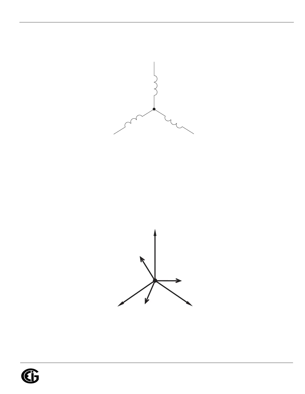
Figure 1.1: Three-phase Wye Winding
The three voltages are separated by 120
o
electrically. Under balanced load conditions
the currents are also separated by 120
o
. However, unbalanced loads and other
conditions can cause the currents to depart from the ideal 120
o
separation. Three-
phase voltages and currents are usually represented with a phasor diagram. A phasor
diagram for the typical connected voltages and currents is shown in Figure 1.2.
Figure 1.2: Phasor Diagram Showing Three-phase Voltages and Currents
N
Phase 1
Phase 3
Phase 2
V
C
V
A
V
B
V
B
N
I
B
I
A
I
C