MX-M316N EXTERNAL VIEW AND INTERNAL STRUCTURE 4 – 15
1
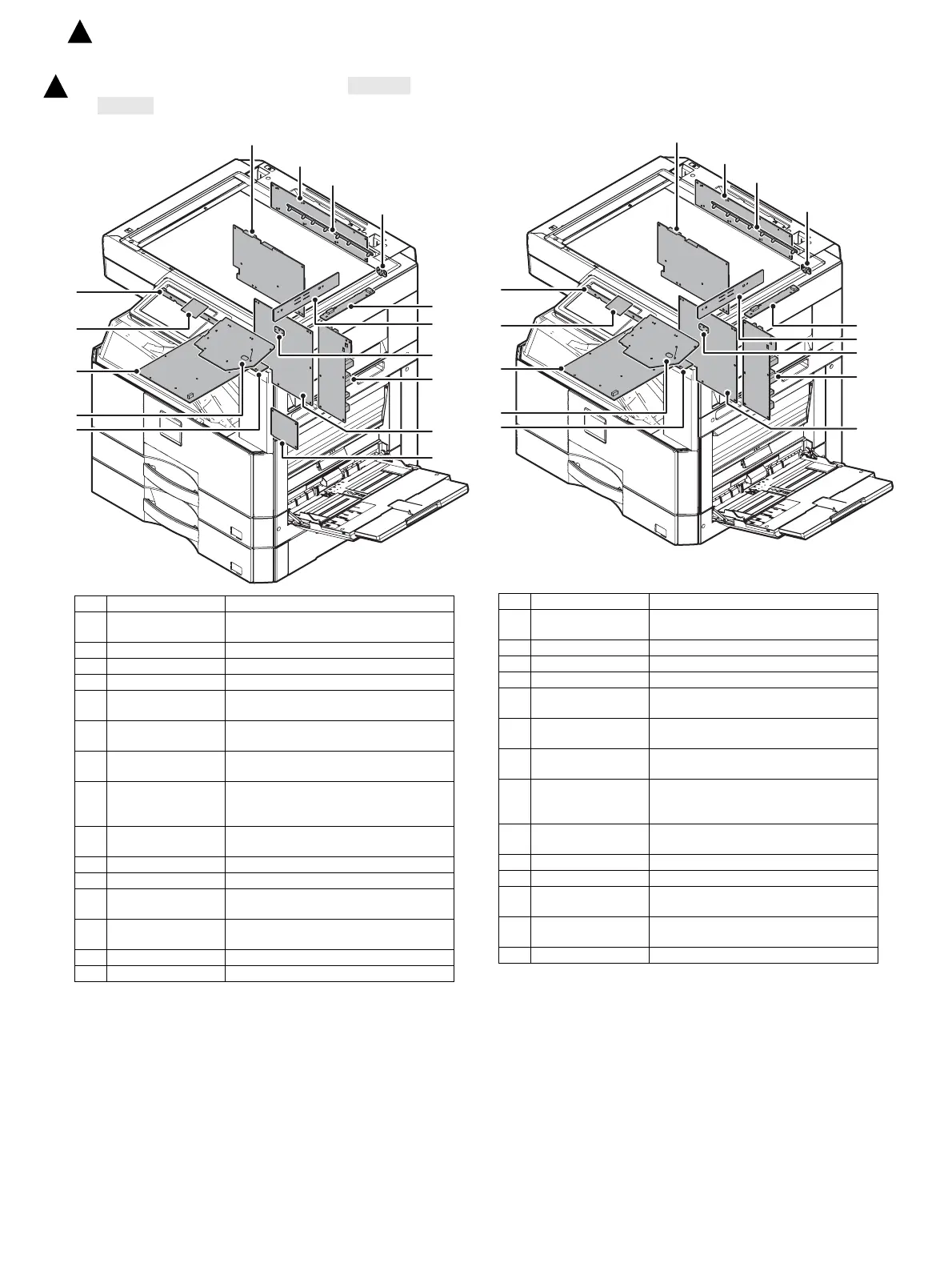
13. PWB
A. MX-M316N/M266N/M315N/M315U/M356N/
M356U
B. MX-M265N/M265U
No. Name Function and operation
1 CCD PWB Scans document images and performs A/D
conversion of the scanning signal.
2 High voltage PWB High voltage control
3 KEY PWB Outputs the key operation signal.
4 LED drive PWB Copy lamp control
5 LED PWB-F Irradiates a manuscript with light for CCD to
read a manuscript image.
6 LED PWB-R Irradiates a manuscript with light for CCD to
read a manuscript image.
7 LVDS PWB Converts the display data signal to the LCD
display signal. Controls the touch panel.
8 MFP control PWB Controls image data (compression,
decompression, and filing), and controls the
whole machine.
9 ORS LED PWB Drives the LED for the document size
detection.
10 ORS-PD PWB Outputs the document size detection signal.
11 PCU PWB Controls the engine section.
12 DC power supply
PWB
DC voltage control
13 SCN CNT PWB Controls the scanner and the operation
section.
14 USB I/F PWB USB I/F
15 Tray interface PWB 2nd tray control
No. Name Function and operation
1 CCD PWB Scans document images and performs A/D
conversion of the scanning signal.
2 High voltage PWB High voltage control
3 KEY PWB Outputs the key operation signal.
4 LED drive PWB Copy lamp control
5 LED PWB-F Irradiates a manuscript with light for CCD to
read a manuscript image.
6 LED PWB-R Irradiates a manuscript with light for CCD to
read a manuscript image.
7 LVDS PWB Converts the display data signal to the LCD
display signal. Controls the touch panel.
8 MFP control PWB Controls image data (compression,
decompression, and filing), and controls the
whole machine.
9 ORS LED PWB Drives the LED for the document size
detection.
10 ORS-PD PWB Outputs the document size detection signal.
11 PCU PWB Controls the engine section.
12 DC power supply
PWB
DC voltage control
13 SCN CNT PWB Controls the scanner and the operation
section.
14 USB I/F PWB USB I/F
1
: ‘15/Aug.