228-90095F
11
3.2 Electrical system
The electrical system can be separated into four major sections, the signal
processing circuits, the light source power supply circuits, the drive circuits
(grating, filters and mirrors), and key board (operator controls).
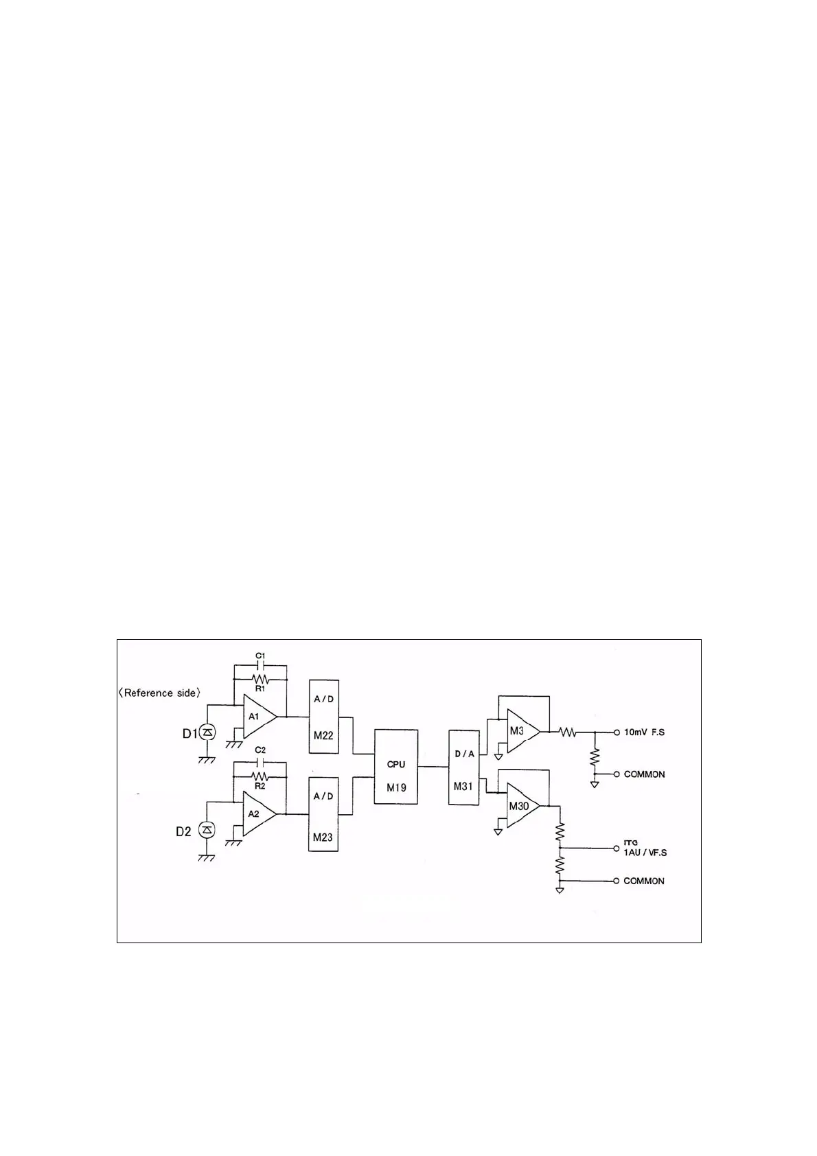
3.2.1 Signal processing circuits
After passing through the measurement and reference cells, the respective light
beams (intensity) I
M and IR enter silicon photodiodes D2 and D1. These
photodiodes generate an electrical current that is proportional to the quantity of
light. The currents K2I
M and K1IR generated from D2 and D1 each flow
respectively through high resistances R2 and R1 and are converted to voltage by
A2 and A1. The respective outputs from A1 and A2 are converted to digital
signals by AD converters M22 and M23 and those values are converted by
logarithmic transformation in the CPU. The CPU processes the absorbance range,
zero adjustment and signal response from values entered via the operator
controls. The logarithmically transformed output voltages are reconverted to
analog voltage using a DA converters (M30 and M31) and a portion of that
voltage is sent via resistors to the AUX terminal as integrator output. Similarly,
resistors are also used to output 10 mV signals as data recorder output.
Schematic of signal processing circuits
Measurement side
 Loading...