228-90095F
2
6.3.7 Adjusting M2
(1) Remove the M2 jig and attach the M2 assembly.
Attach the M3 jig to assembly M3. Press the function key and set “Z
WAVE”, in the factory group, to 3.
(Wavelength still = 0nm)
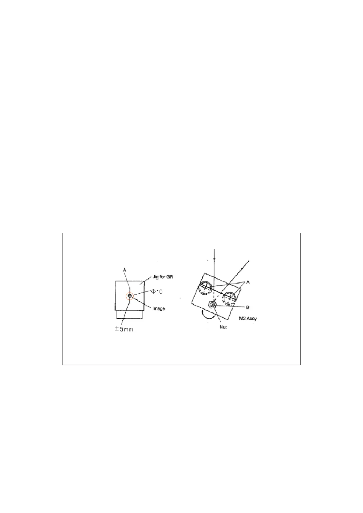
(2) Roughly adjust the rotation of M2 and GR so the 0-order light from M2
passes via GR and is laterally centered on M3 (within Φ10mm circle).
Next, attach the GR jig and adjust the M2 assembly rotation so the light
image is laterally centered on the GR target mark. Roughly adjust the
vertical angle of M2 at this point. (Rotation: Adjust by loosening screws
“A” and rotating. Elevation: Adjust by loosening nut and turning set screw
“B”.)
(3) After making adjustments, tighten screws “A” and remove the GR jig, but
don’t tighten the nut at this point.
 Loading...