228-90095F
4
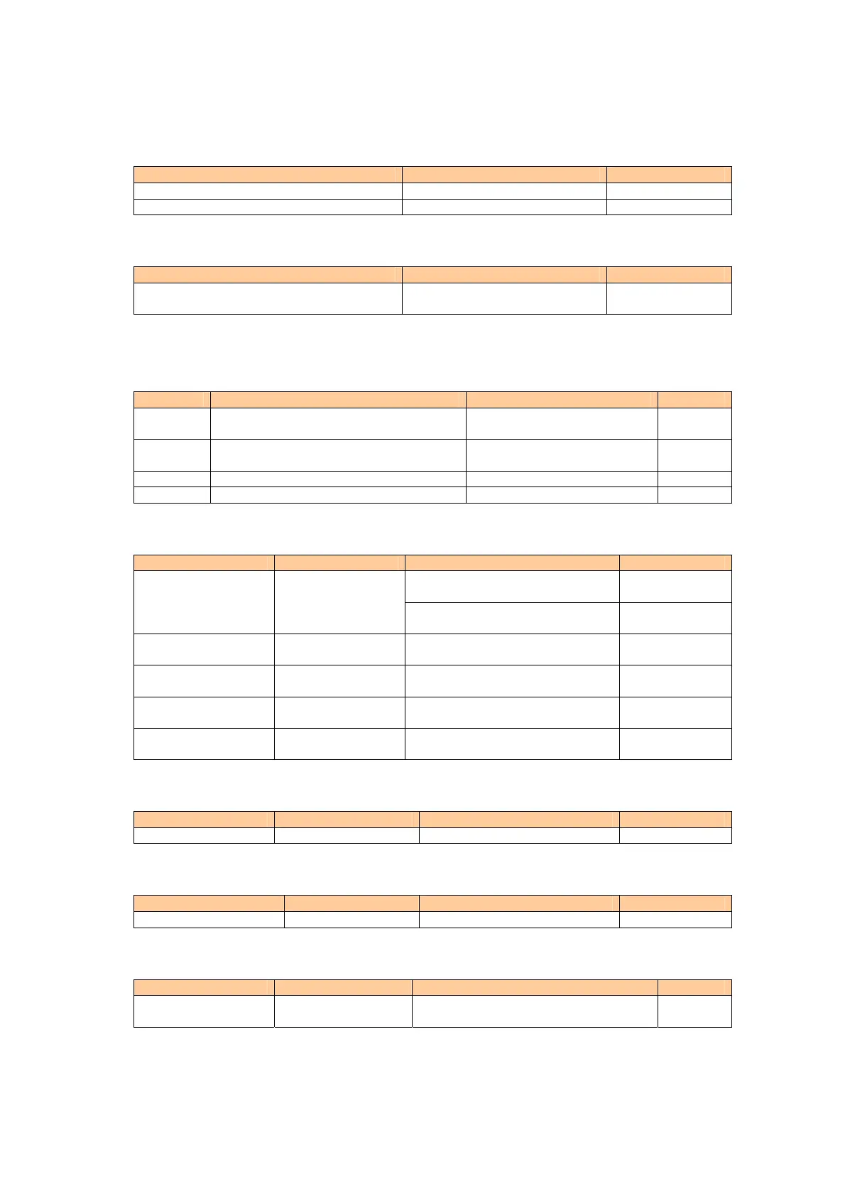
8.3.1.11 EEPROM writing and NMI function circuits
Item Points to check
NOT PROTECTED occurs R/C around M29, M15, M29 NMI, EEPROM
Value settings are not recorded M15 EEPROM
8.3.1.12 HDLC transmission functions (optional) circuit
Item Points to check
Cannot communicate with external
devices
M14, M21, M26, J14, J15
8.3.2 SPD20-PWR(POWER) circuit board
8.3.2.1 Reference voltages
Item Allowable range Points to check
±12V
+12V: +12 ±1V across P5-P8
-12V: -12 ±1V across P5-P9
C14, M10, M11, F5, F6, C46
-- C48, C51 -- C53, D13, D15
D5V
+5 ±0.5V across P1-M13 (8-pin)
+5 ±0.5V at C59, M13 (8-pin)
J6, M13, C59
24V +26V±5V across P1-P7 D12, F3, F4, C44, C45
18V +18V±2V across P1-P10 M12, C57, C58
8.3.2.2 MAIN (CPU) PCB interface circuit
Item Allowable range Points to check
M5, M8, M9, Q5, L2, D16, R57,
R58
Heater circuit
D2 lamp does not go
on/off
M4, M6, K1, K2, R26, R27, F1,
Q2, Q3
Anode circuit
Abnormal [LAMP
CUR] value
300 ±30
R/C around M4, M6, M8, Q2, Q3,
F1, R26, R27, M8
Abnormal [D2 FIL
CUR] value
700 ±100 R/C around M8, R47, M8
W lamp does not go
on/off
R/C around M2, M3, M5, Q4, L1,
D11, R32, R33,R19, M2
Abnormal [W FIL
CUR] value
1500 ±200 R/C around M2, R19, M2
8.3.2.3 ecycle valve and VFC control ci
rcuits
Item Allowable range Points to check
5-8 pin voltage 13 ±3V M1, J2, R14, NF2 -- NF5
8.3.2.4 Cooling fan control circuit
Item Allowable range Points to check
Cannot control fan M12, J7, J9
8.3.2.5 Flow cell temperature c
ontrol circuit
Item Allowable range Points to check
Abnormal temp
display values
40 ±1C
R/C around M2, M13, Q7, J4, R65,
M2/M13