228-90095F
3
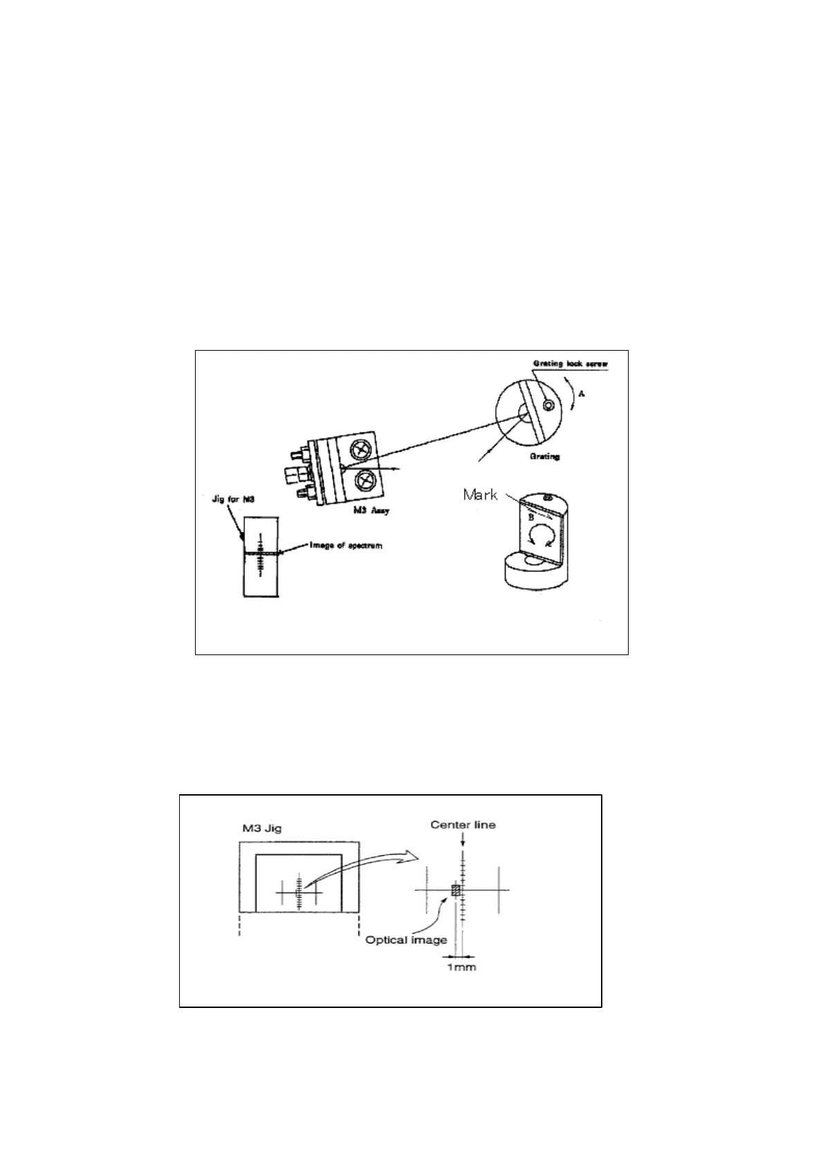
6.3.8 Adjusting the grating
> It continues. Z-wave =3.λ=0nm
(1) Rotate the grating in direction “A” shown in the figure and look at the
spectrum projected on M3. Loosen the grating lock screw and rotate the
grating in direction “B” in the figure. Secure the grating in location when
the spectrum becomes horizontal.
(2) Readjust the vertical angle of assembly M2 so the image is vertically
centered on the M3 jig and tighten the nut.
(3) Adjust the grating by rotating it in direction “A” shown above until the
0-order light image reaches a lateral position on the M3 jig that is 1 mm
(±0.3 mm) to the left of center.
(4) Remove the M3 jig.