10
2 Name and functions of sections
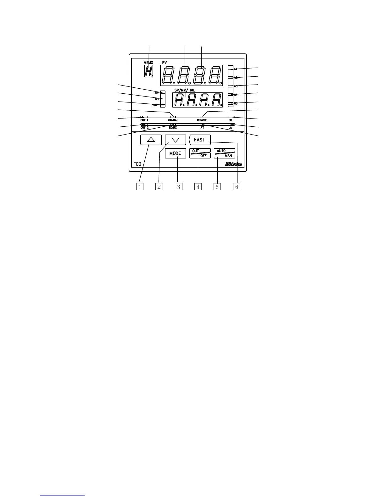
2.1 Name of sections
(3) (2) (1)
(11)
(12)
(4) (13)
(5) (14)
(6) (15)
(7) (16)
(8) (17)
(9) (18)
(10) (19)
(Fig. 2.1-1)
(1) PV display (Red)
Indicates the PV or setting characters in the setting mode.
(2) SV/MV/TIME display (Green)
Indicates the SV, MV, Time or each set value in the setting mode.
(3) MEMO display (Yellow)
Indicates the Set value memory number.
(4) SV indicator (Green)
Lights while the SV is indicated on the SV/MV/TIME display.
(5) MV indicator (Red)
Lights while the MV is indicated on the SV/MV/TIME display.
(6) TIME indicator (Yellow)
Lights while the Time is indicated on the SV/MV/TIME display.
(7) MAN indicator (Red)
Lights during Manual control.
(8) OUT1 indicator (Green)
Lights when the Control output (OUT1) is on.
(For the DC current output type, it flashes in 125ms cycles corresponding to the MV.)
(9) OUT2 indicator (Yellow) (Option)
Lights when the Control output (OUT2) is on.
(For the DC current output type, it flashes in 125ms cycles corresponding to the MV.)