18
5. Wiring
Warning
Turn the power supply to the instrument off before wiring or checking.
Working or touching the terminal with the power switched on may result in
severe injury or death due to Electric Shock.
Moreover, the instrument must be grounded before the power supply to the
instrument is turned on.
Caution
• Do not leave wire remnants in the instrument, because they could cause a fire or malfunction.
• Use a solderless terminal with an insulation sleeve in which the M3 screw fits when
wiring the instrument.
• Tighten the terminal screw using the specified torque. If excessive force is applied to
the screw when tightening, the terminal screw or case may be damaged.
• The terminal block of this instrument is designed to be wired from the left side.
The lead wire must be inserted from the left side of the terminal, and fastened by the
terminal screw.
• Do not apply a commercial power source to the sensor which is connected to the input
terminal nor allow the power source to come into contact with the sensor.
• Use a thermocouple and compensating lead wire according to the sensor input
specifications of this controller.
• Use a 3-wire RTD system corresponding to the input specifications of this controller.
• This controller does not have a built-in power switch, circuit breaker or fuse.
Therefore, it is necessary to install them in a circuit near the external controller.
(Recommended fuse: Time-lag fuse, rated voltage 250V AC, rated current 2A)
• For a 24V AC/DC power source, do not confuse polarity when using direct current (DC).
• When using a relay contact output type, use a relay according to the load capacity to
protect the built-in relay contact.
• When wiring, keep input wires (thermocouple, RTD, etc.) away from AC sources or
load wires.
• Use a thick wire (1.25 to 2.0mm
2
) for grounding.
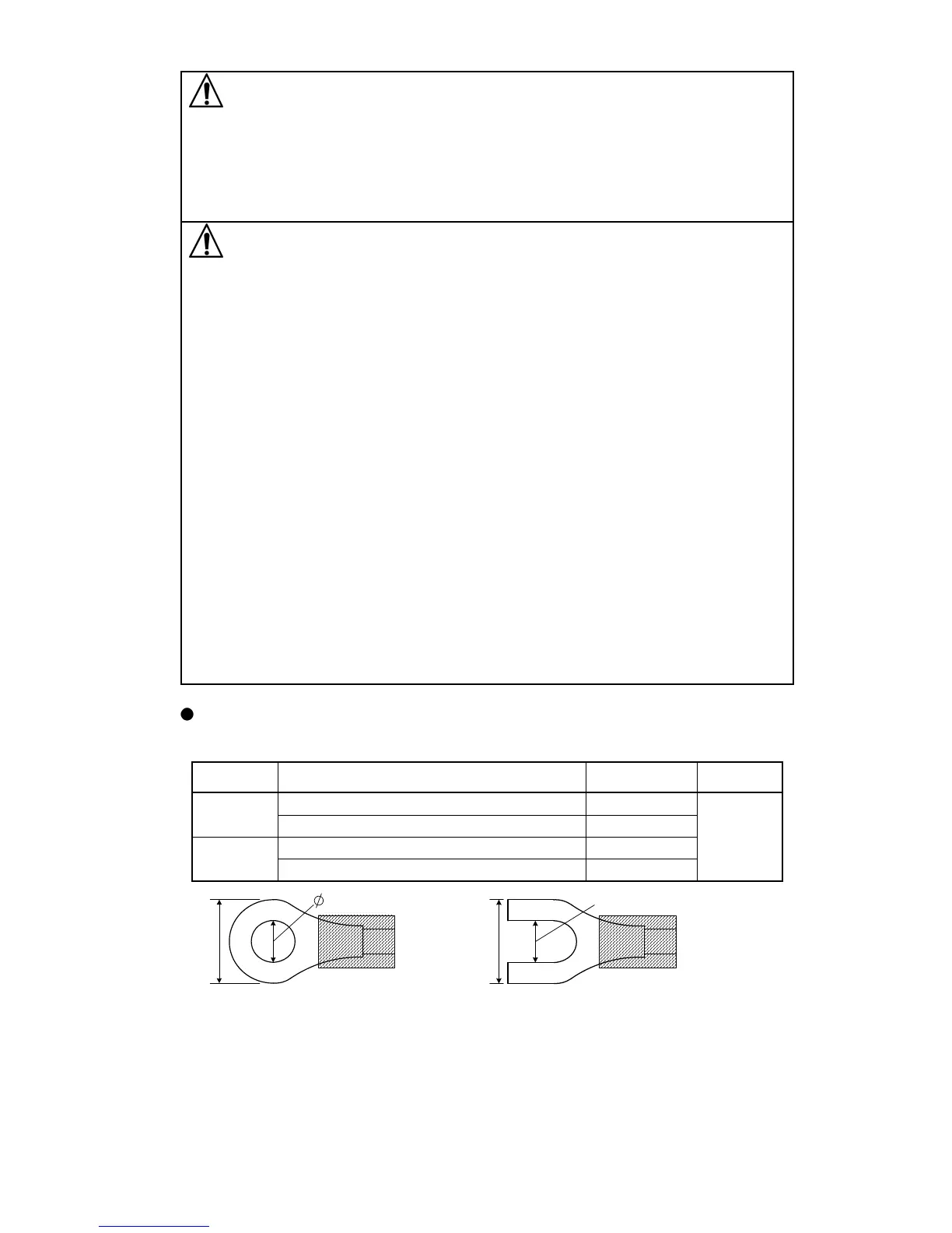
Lead wire solderless terminal
Use a solderless terminal with an insulation sleeve in which an M3 screw fits as shown
below. The torque should be 0.63N•m.
Solderless
terminal
Manufacturer Model Torque
Y type
Nichifu Terminal Industries CO.,LTD. TMEV1.25Y-3
0.63N•m
Japan Solderless Terminal MFG CO.,LTD. VD1.25-B3A
Ring type
Nichifu Terminal Industries CO.,LTD. TMEV1.25-3
Japan Solderless Terminal MFG CO.,LTD. V1.25-3
(Fig. 5-1)
3.2mm
5.8mm or less
3.2mm
5.8mm or less