12
3. Setup
3.1 Taking the internal assembly out
Before the power supply to this instrument is turned on, take the internal assembly out
from the case in the direction indicated by the arrow by pushing the latch (bottom of the
instrument) while holding the instrument by the top and bottom.
(Fig. 3.1-1)
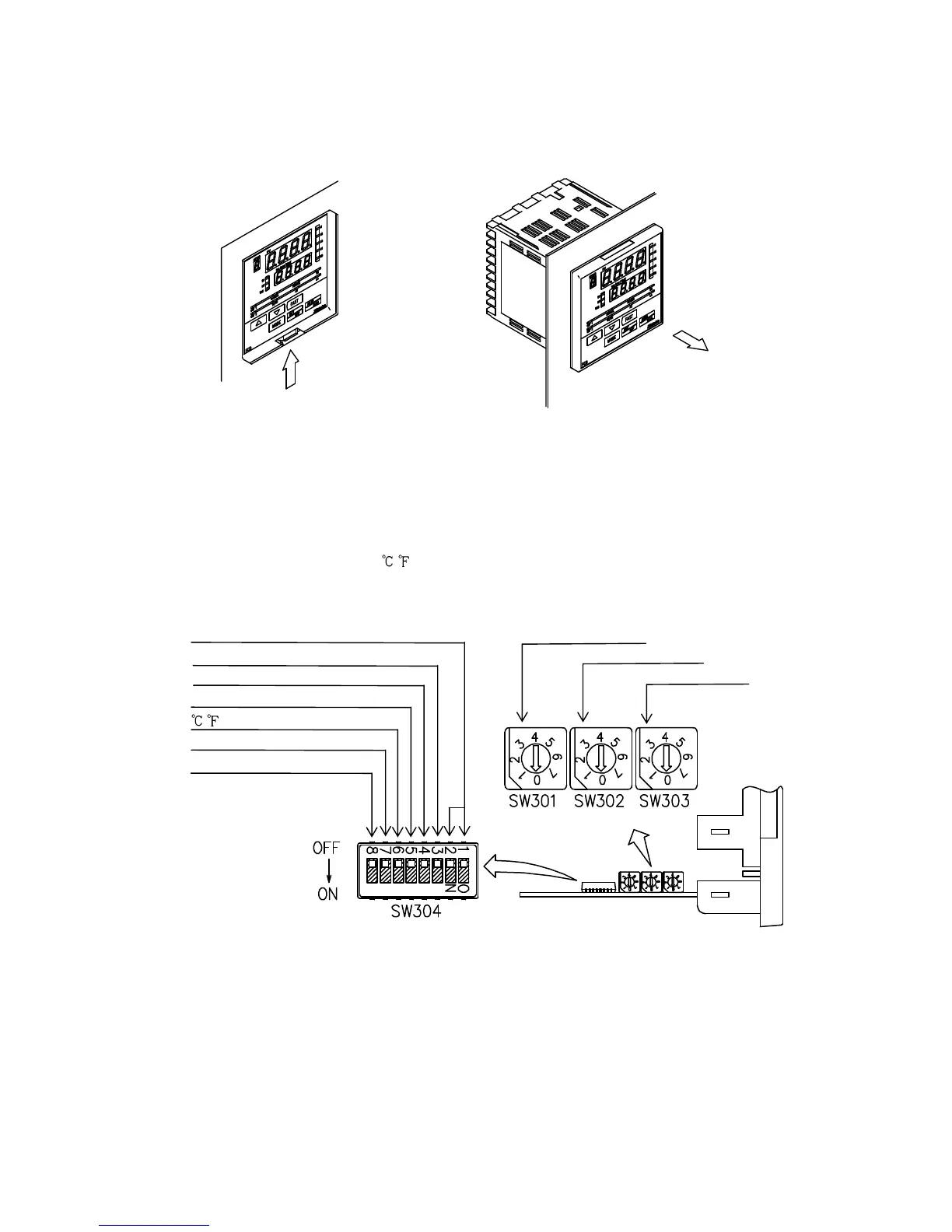
3.2 Switch setting (multi-function)
Using a small flat blade screwdriver and tweezers, set the following with the DIP and
Rotary switches.
Sensor input, Alarm 1 (A1) type, Alarm 2 (A2) type, Control action,
Heating (reverse)/Cooling (direct) action, Alarm 1 (A1) and Alarm 2 (A2)
standby function, Unit
/ and Program start Auto/Manual
Rotary switch (SW301) will be equipped only when A2 option is added.
Control action Alarm 2 (A2) type
Heating/Cooling action Alarm 1 (A1) type
Alarm 1 (A1) standby action Sensor input
Alarm 2 (A2) standby action
/
Sensor input
Program start Auto/Manual
(Fig. 3.2-1)
DIP switch
Rotary switch