19
11
12
13
14
15
16
17
18
19
20
31
21
22
23
24
25
26
27
28
29
30
32
33
34
35
36
37
38
39
1
2
3
4
5
6
9
10
TX[YA(-)]
RX[YB(+)]
b0
b1
b2
COM
RS-232C
[RS-485]
SM
TA or TV
A3
A4
18
19
100 to 240V AC
or 24V AC/DC
A1/P.END1
H
OUT1(R/M) C
L
Ground
18
19
17
18
19
5
6
+
-
OUT1(S/M or A/M)
+
-
mA DC
+
-
V DC
A
B
B
RTD
TC
+
-
+
-
+
-
+
-
CT1
CT2
W or W3
R/L
A/M
COM
EA or EV
7
8
OUT2(DR)/A2/
P.END2/LA/P24
7
8
OUT2(DS, DA)/A2/
P.END2/LA/P24
+
-
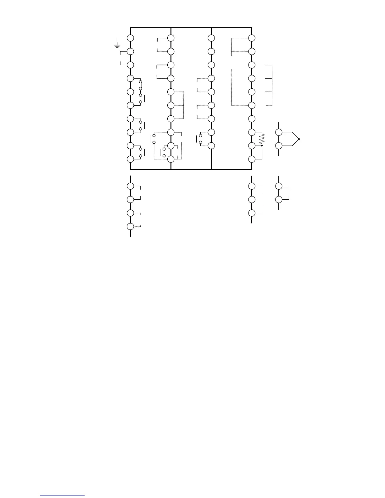
5.1 Terminal arrangement
(Fig. 5.1-1)
Dotted lines show options, and no terminal is equipped unless specified.
If Alarm 2 (Pattern end 2 output) and Loop break alarm are added together, they
utilize common output terminals.
OUT1 Control output 1
OUT2 Control output 2
A1 to A4 Alarm 1 to Alarm 4 output
P.END1, 2 Pattern end 1, 2 output (simplified program controller function)
LA Loop break alarm output
P24 Insulated power output
RS-232C[RS-485] Serial communication
SM Set value memory number external selection
TC Thermocouple input
RTD RTD input
DC DC voltage, current input
TA or TV Transmission output
EA or EV External setting input
R/L, A/M External operation: Remote/Local, Auto/Manual (EA, EV option
should be added) (See p. 21.)
CT1, CT2 CT1 input (W, W3 option), CT2 input (W3 option)
W or W3 Heater burnout alarm output