11
(10) TX/RX indicator (Green) (Option)
Lights during Serial communication [TX (transmitting) output].
(11) A1 indicator (including Pattern end 1 output) (Red)
Lights when the Alarm 1 (A1) output or Pattern end 1 output is on.
(12) A2 indicator (including Pattern end 2 output) (Option) (Red)
Lights when the Alarm 2 (A2) output or Pattern end 2 output is on.
(13) A3 indicator (Red) (Option)
Lights when the Alarm 3 (A3) output is on.
(14) A4 indicator (Red) (Option)
Lights when the Alarm 4 (A4) output is on.
(15) HB indicator (Red) (Option)
Lights when the Heater burnout alarm output is on.
(16) REMOTE indicator (Red) (Option)
Lights during Remote action.
(17) SB indicator (Red)
Lights when Sensor is burnt out.
(18) LA indicator (Red) (Option)
Lights when the Loop break alarm output is on.
(19) AT indicator (Yellow)
Flashes during AT (auto-tuning).
2.2 Keys
Main functions are described below, however, the keys have other functions depending
on modes. Refer to Section “6.1 Operation flowchart“.
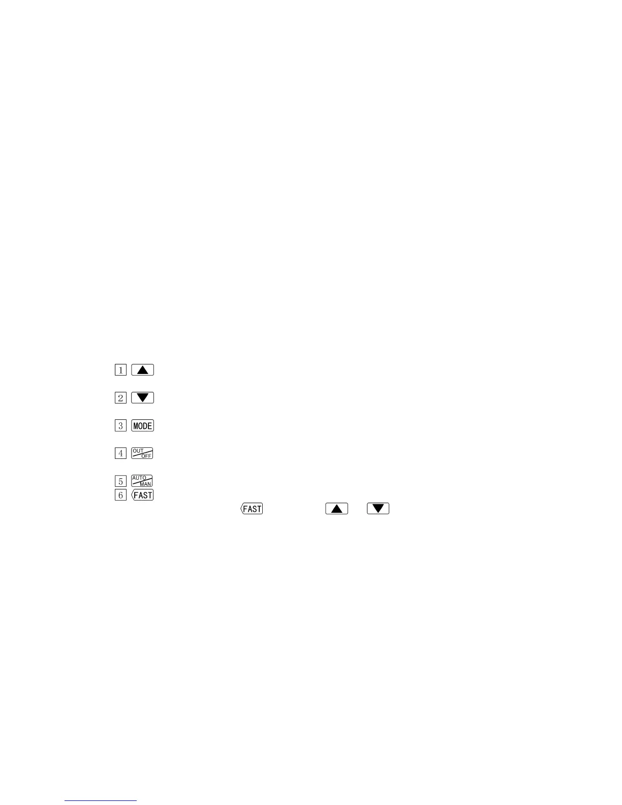
Increase Key : Increases the numeric value on the SV/MV/TIME display
during setting mode.
Decrease Key : Decreases the numeric value on the SV/MV/TIME display
during setting mode.
Mode Key : Switches a setting mode and registers set values.
(To register each set value, press this key.)
OUT/OFF Key : Performs the control output ON or OFF.
Starts/Stops the program control.
Auto/Manual Key : Switches either Automatic control or Manual control.
Fast Key : Makes the numerical value change faster by pressing the
key with the or key simultaneously.