Output status when input abnormal
• Selects control output status when DC input is in
overscale or underscale.
• Available only for DC input
• Selection item:
Outputs
OFF(4mA) or
OUT1(OUT2)
low limit
value.
: Outputs OFF(4mA) or OUT1(OUT2) low limit value.
: Outputs a value between OFF(4mA) and ON(20mA) or
between OUT1(OUT2) low limit value and OUT1(OUT2) high
limit value, depending on a deviation.
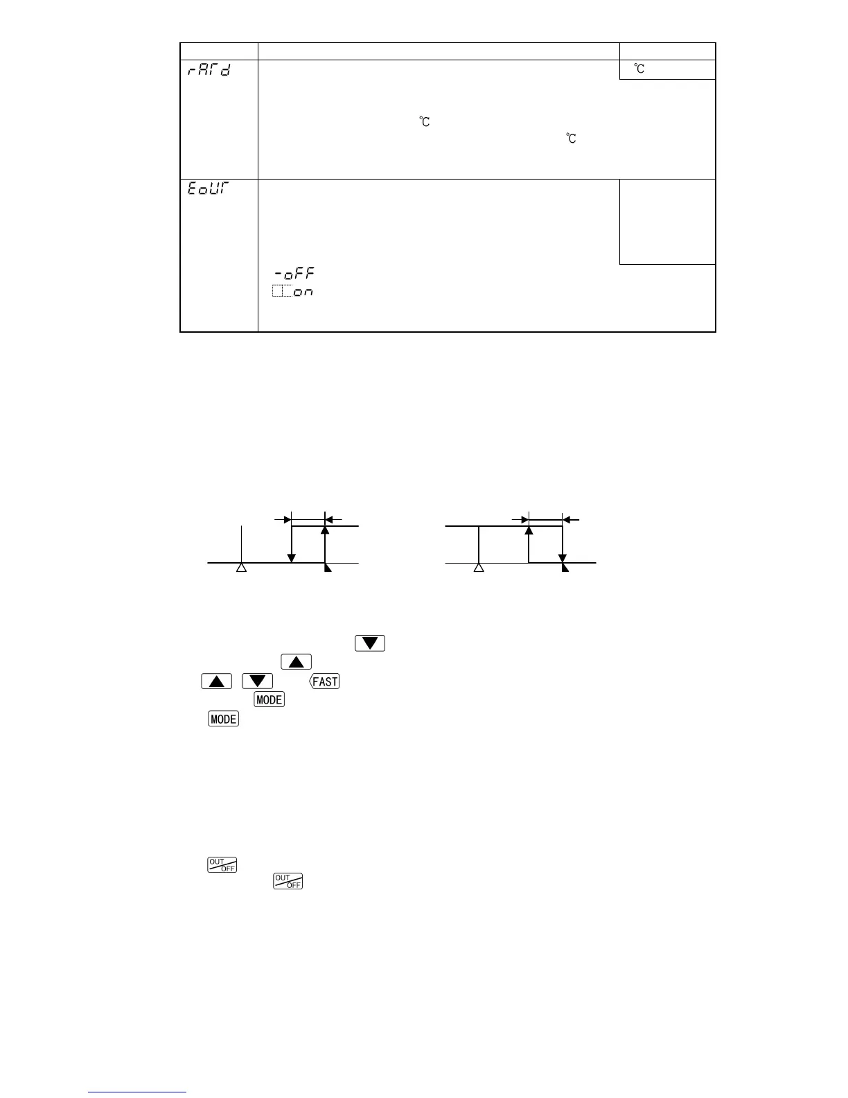
Alarm 1 to 4 Energized/De-energized function
[If the alarm action Energized is selected]
When the alarm output indicator is lit, the alarm output (terminals 7-8, 9-10, 28-30, 29-30)
is conducted (ON). When the alarm output indicator is unlit, the alarm output is not
conducted (OFF).
[If the alarm action De-energized is selected]
When the alarm output indicator is lit, the alarm output (terminals 7-8, 9-10, 28-30, 29-30)
is not conducted (OFF). When the alarm output indicator is unlit, the alarm output is
conducted (ON).
High limit alarm (when Energized is set) High limit alarm (when De-energized is set)
A1: Alarm 1. For A2 (A3, A4), read “A2 (A3, A4)” for “A1”.
6.2.5 Program mode
In PV/SV display mode, if the
key is pressed for approximately 3 seconds while
holding down the
key, the units moves to the Program mode.
The
, and keys increase or decrease the set values (numeric value).
Pressing the
key registers the set value, and proceeds to the next setting item.
If the
key is pressed at the last setting item, the set value is registered, and the
unit reverts to the PV/SV display mode.
• Each set value of Set value memory numbers (1 to 7) set during the Fixed value control
are assigned to the values for Steps 1 to 7 respectively.
For example, values of Set value memory number 1 become Step 1 values, and values
of Set value memory number 2 become Step 2 values.
• If the Pattern end output is selected and the program control is performed, the Pattern
end output is turned on when the program is completed.
• If the
key is pressed while the Pattern end output is on, the Pattern end output is
turned off. If the
key is pressed again, the program will be performed.
(Fig. 6.2.4-1)