22
6. Settings
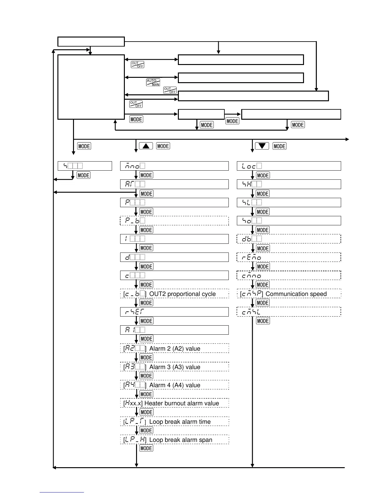
6.1 Operation flowchart
Power ON
(*1) (*1)
Control output OFF function (Fixed value control)
Manual control (Fixed value control)
(*1)
Standby mode (Program control)
MV indication Remaining step time indication (*2)
[Main setting mode] [Sub setting mode] [Auxiliary function setting mode 1]
[
] SV [ ] Set value memory number [ ] Set value lock
[ ] AT Perform/Cancel (*3) [ ] SV high limit
[ ] OUT1 proportional band [ ] SV low limit
[ ] OUT2 proportional band [ ] Sensor correction
[ ] Integral time [ ] Overlap/Dead band
[ ] Derivative time [ ] Remote/Local
[ ] OUT1 proportional cycle [ ] Instrument number
[ ] OUT2 proportional cycle [ ] Communication speed
[ ] Manual reset [ ] Communication protocol
[ ] Alarm 1 (A1) value
[ ] Alarm 2 (A2) value
[ ] Alarm 3 (A3) value
[ ] Alarm 4 (A4) value
[ xx.x] Heater burnout alarm value
[ ] Loop break alarm time
[ ] Loop break alarm span
+
+ (appprox. 3sec)
(approx. 1sec)
(approx. 1sec)
(approx. 3sec)
PV/SV display mode