15
The alarm type and the pattern end output for program control can be selected by
the Rotary switch (SW302) and (SW301).
Rotary switch (SW301) will be equipped only when the A2 option is added.
Rotary SW302: Alarm 1 (A1) type or Pattern end 1 output
Rotary SW301: Alarm 2 (A2) type or Pattern end 2 output
Note: If an alarm type is changed, the alarm set value becomes 0 (0.0).
Default value: No alarm action
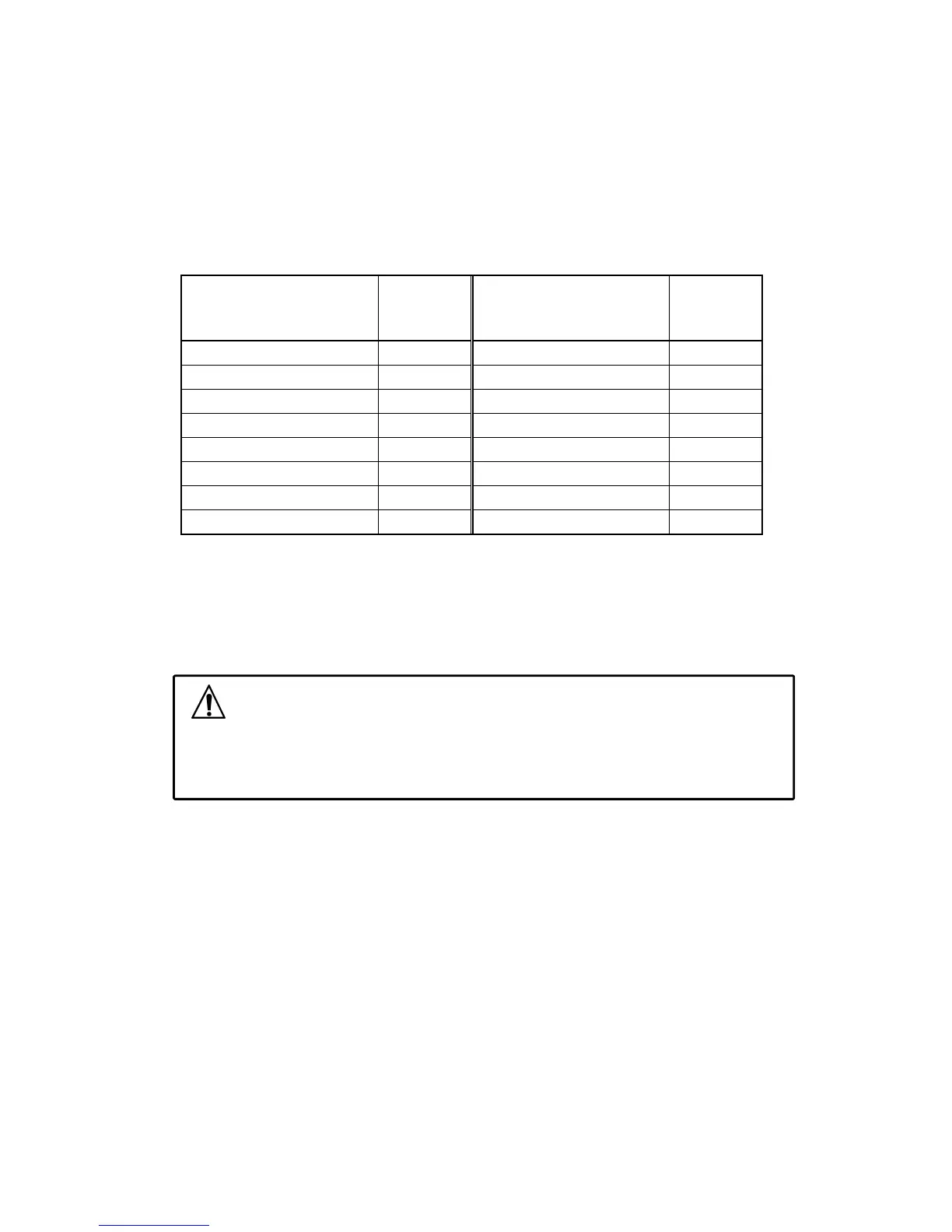
(Table 3.2-3)
Alarm 1 (A1) type
Rotary
SW302
No.
Alarm 2 (A2) type
Rotary
SW301
No.
No alarm action 0 No alarm action 0
High limit alarm 1 High limit alarm 1
Low limit alarm 2 Low limit alarm 2
High/Low limits alarm 3 High/Low limits alarm 3
High/Low limit range alarm 4 High/Low limit range alarm 4
Process high alarm 5 Process high alarm 5
Process low alarm 6 Process low alarm 6
Pattern end 1 output 7 Pattern end 2 output 7
3.3 Insertion of the internal assembly
After the setup is completed, insert the internal assembly into the case.
Firmly insert the assembly until it is locked by the latch at the bottom of the instrument.
(There will be a clicking sound.)
Caution
Do not confuse the top and bottom of the internal assembly.
If inserting the assembly into the case by force in the wrong direction, the PCB may be
damaged.