28
[A1, A2, A3 and A4 setting range]
Alarms with the standby function have the same setting range.
(Table 6.2.2-1)
Alarm type Setting range
High limit alarm –Input span to Input span ( ) *1
Low limit alarm –Input span to Input span ( ) *1
High/Low limits alarm 0 to Input span ( ) *1
High/Low limit range alarm 0 to Input span ( ) *1
Process high alarm Input range low limit to Input range high limit *2
Process low alarm Input range low limit to Input range high limit *2
• For RTD input, the negative low limit value is –199.9.
• For DC input, the negative low limit value is –1999.
(The placement of the decimal point follows the selection.)
*1: For DC input, the Input span is the same as the Scaling span.
*2: For DC input, Input range low (or high) limit value is the same as the Scaling low
(or high) limit value.
6.2.3 Auxiliary function setting mode 1
In the PV/SV display mode, if the
key is pressed for approx. 3 seconds while
holding down the
key, the unit proceeds to Auxiliary function setting mode 1.
The set value can be increased or decreased by pressing the
, and
keys.
Pressing the
key registers the set value and proceeds to the next setting item.
If the
key is pressed at the last setting item, the set value will be registered and
the unit will revert to the PV/SV display mode.
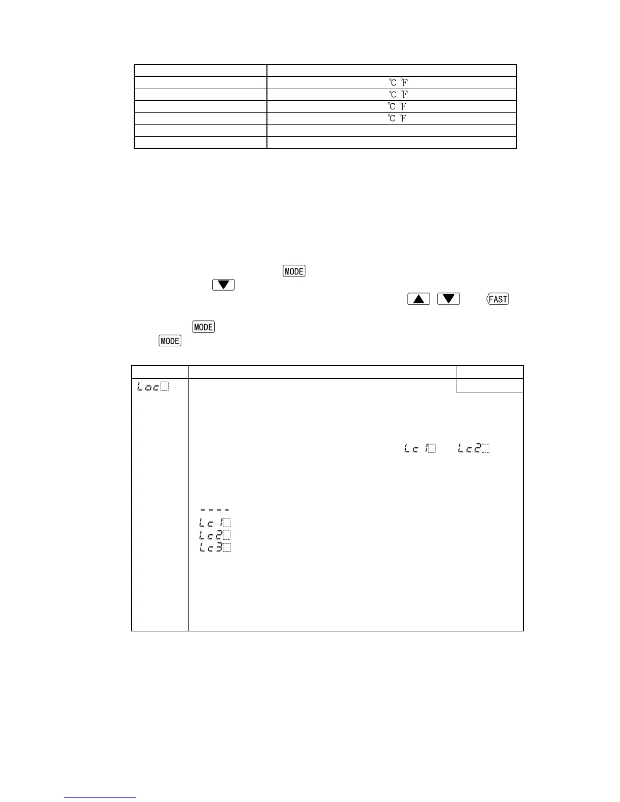
Character Name, Function, Setting range Default value
Set value lock Unlock
• Locks the set value to prevent setting errors.
The setting item to be locked differs depending on the selection.
• When selecting Lock, set the necessary items in the status Unlock, then
select Lock 1, Lock 2 or Lock 3.
• Fuzzy self-tuning or AT will not function if [
] or [ ] is
selected.
• Be sure to select Lock 3 when changing the set value frequently via
communication function considering the life of non-volatile memory.
• Selection item:
(Unlock): All set values can be changed.
(Lock 1): None of set values can be changed.
(Lock 2): Only SV can be changed.
(Lock 3): All set values can be changed temporarily. However,
changed values revert to their previous value after
power-off because they are not saved in the
non-volatile memory.
Since this function has no relation to the memory life,
it is well suited when using with Shinko programmable
controllers (with SVTC option).