Operating Instructions Chapter 3
C4000 Select
8012247/RI61/2007-11-30 © SICK AG • Industrial Safety Systems • Germany • All rights reserved 19
Product description
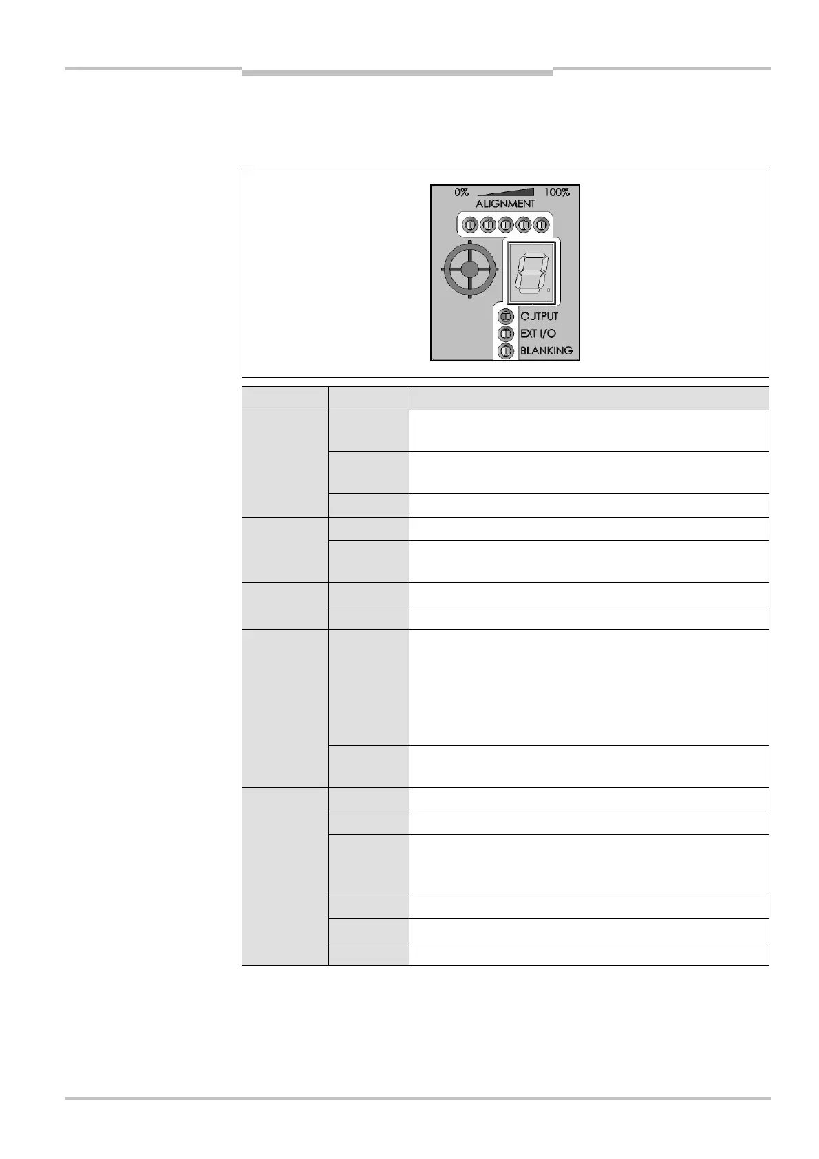
3.4.2 Message center of the C4000 Select receiver unit
The message center for the C4000 Select receiver unit consists of several LED groups and
a 7@segment LED display that provides operational status as shown in the figure below:
LED Name Display Meaning
Green Output signal switching devices (OSSD)/safety outputs
are ON
Red Output signal switching devices (OSSD)/safety outputs
are OFF
OUTPUT
Off No power is currently supplied to the receiver unit
Red Extended I/O safety inputs are Inactive (Low) i.e. OFFEXT I/O
Off Extended I/O safety inputs are Active (High) i.e. ON or
Extended I/O has been disabled
Yellow Blanking is activeBLANKING
Off Blanking is inactive
Yellow Indicates that one or more beams are aligned between sen-
der and receiver units. The first LED will be Yellow when
one of the synchronization beams has been aligned. When
all five (5) LEDs are Yellow, this indicates all beams are
aligned between sender and receiver units, but there is a
weak signal.
ALIGNMENT
LEDs
Green When all five (5) LEDs are Green, this indicates that all
beams are aligned between sender and receiver units.
An internal error has been detected. Replace receiver unit.
Check DIP switch settings
Optical signals have been detected from multiple sender
units. Change beam code of this C4000 Select
sender/receiver pair.
Check power supply voltage
Check system wiring for errors
7?segment
display
Check extended I/O wiring for errors
C4000 Select receiver unit
ver LED display indication